3-D - What's New?

Service Pack 1 2021 (V 2601)
AutoQuickView
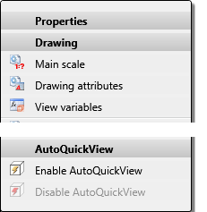
The previous user guidance texts in the context menu of the drawing at Properties > AutoQuickView as well as in the Properties function group of the Drawing Ribbon tab have been changed to emphasise the automatic aspect more clearly.
The function Enable AutoQuickView switches the AutoQuickView on. This automatism sets one or more views to QuickView mode - at the given time - in order to skip HiddenLine and Glass model calculations.
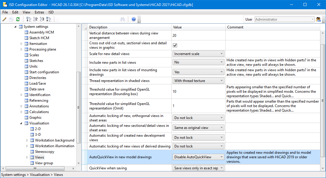
The change of the user guidance text also concerns the settings in the Configuration Editor.
Standard Parts / Standard Processings
Boltings - User-specific threads
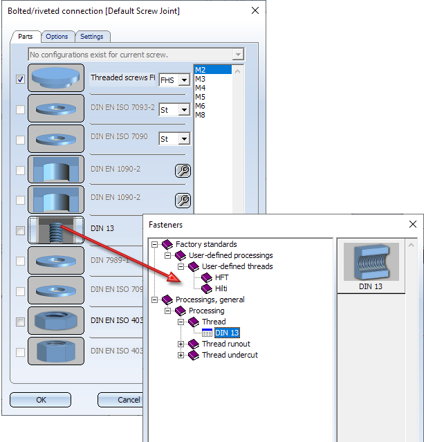
From SP1 onwards, user-defined threads can be selected from the catalogue Factory standards > User-defined processings > User-defined threads - depending on the selected screw/bolt type - when inserting boltings in your model drawing.
Spherical plain bearing
The revision of the display of bearings started with HiCAD 2021 has been continued in SP1 with the revision of the spherical plain bearings and spherical plain bearing rod ends. The new parts allow the selection of all edges and surfaces and present themselves as one part in every respect. This applies, for example, to highlighting and part selection..
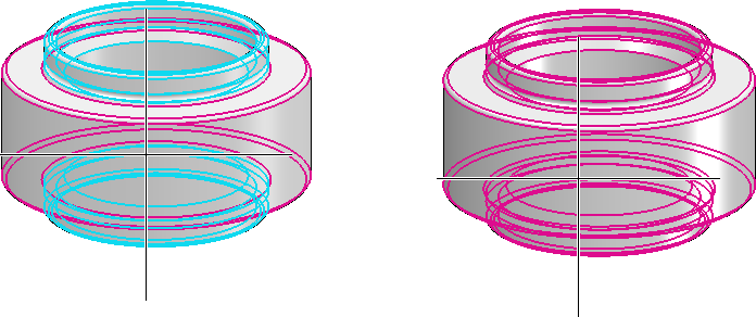
Left: Highlighting in HiCAD 2020, Right: in HiCAD 2021 SP1.
The new representation, however, only affects spherical plain bearings that are integrated into the drawing from HiCAD 2021 SP1. When loading drawings with spherical plain bearings from a version before HiCAD 2021 SP1, the "old" representation is used.
Process / model parts
New part from 3-D sketch
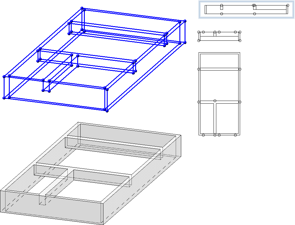
With the new function  New part from 3-D sketch you can derive a solid from a 3-D sketch. This solid consists of planar surfaces and the body edges are the lines of the sketch.
The 3-D sketch must fulfil the following conditions:
- The sketch may only contain straight lines. These must be real lines. For example, straight Nurbs curves and auxiliary geometry are not allowed.
- The lines of the sketch must not intersect or coincide (lie on top of each other).
- The sketch must result in a meaningful solid.
- At least three lines must converge at each line end. Any auxiliary geometry that may exist will not be considered here. Ends with one or two lines are evaluated as errors and displayed in the graphic. In this way, even small gaps in the sketch can be found quickly.
After calling the function, the Part from 3-D Sketch dialogue window is displayed and HiCAD prompts you to select a line of the 3-D sketch.
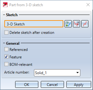
If it is possible to create a solid on the basis of the selected 3-D sketch, then a preview of the part is automatically displayed in the design. With a click on the Apply button (or on OK or by pressing the middle mouse button) the part is created.
If the creation of the 3-D part cannot be carried out, then the  symbol is displayed at the OK button. If the selected sketch does not meet the requirements, the
  symbol appears next to the field for sketch selection. If you point with the cursor to one of the symbols, you will get further information. The corresponding lines and surfaces are visualised in the construction and highlighted in red. You can then correct the sketch or cancel the function.
Divide part
The  Divide function has been completely revised.
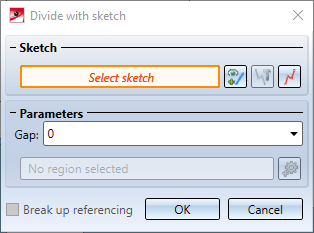
With this function you divide a part based on a planar sketch. Each line of the sketch is a section line that divides the part into two section regions. Connected lines are treated as one line. This means, for example, that a sketch consisting of three connected lines also divides a part into two cutting regions. Each section region can consist of several parts, whereby the number of parts is determined by the actual number of lines.
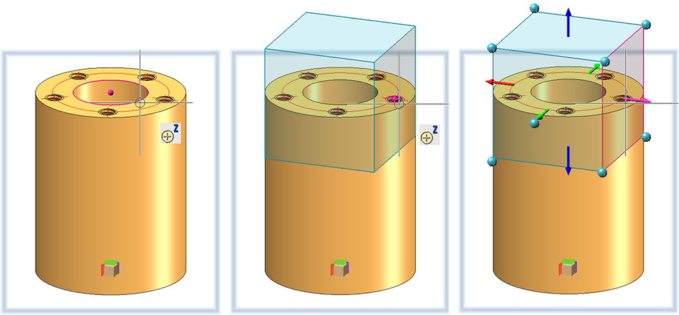
The illustration shows a cuboid with three different sketches and the resulting division. In all cases, two parts are created. In (1) and (3) the leading part consists of two segments in case (2) of one segment.
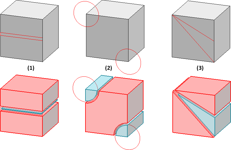
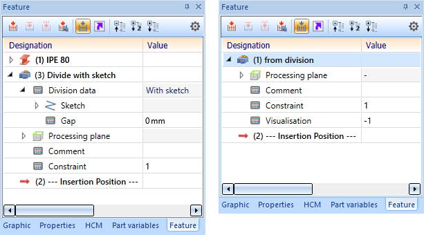
The main feature Divide with sketch is assigned to the leading part (highlighted red when executing the function). With this feature the sketch can be edited later and the gap can be changed. All other parts created are assigned the feature from division.
Divide along direction
The functions Divide along direction  and Divide along direction
  (Steel Engineering > Lengthen > Divide
  > ...) have been revised
- The display of the cut planes in the preview is omitted. Only the division direction and the division points are visualised.
- Dividing can now also be done by selecting points.
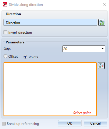
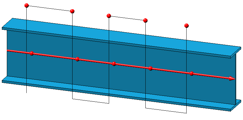
- If the active 3-D part is a beam or profile, the beam/profile axis is automatically suggested as the division axis when the function is called up via the context menu for 3-D parts. The division direction depends on the cursor setting when the function is called.
New Fillet dialogue
The Fillet  dialogue window has had a redesign, now containing additional selection options for elements to be filleted, an improved preview, changed parameters, extended value input options etc.
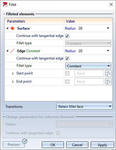
New and enhanced options:
- In addition to the selection of individual edges and surfaces, additional elements can now be selected for filleting via a context menu:
- For edges, the edge direction is visualized. This depends on the cursor setting when selecting the edge.
- Intermediate points for variable filleting can be specified either as a percentage of the length of the edge to be filleted or as a point option. Points that are determined via a point option do not have to be on the composite edge. They are projected automatically.
- It is also possible to fillet segments of edges. The start and end points of a segment can be specified as a percentage or as a point option, just like the intermediate points in variable filleting. However, this applies only to constant filleting!
- Variables and formulas can be used in all input fields.
- The preview has been improved and can now be updated either automatically or by clicking.
- Multiple selection is possible when changing parameters of elements that have already been selected for filleting.
- In Element snap mode, the Fillet function is now also available in the context menu.
- The Rework 3-D corners function is no longer available as of HiCAD 2021 SP1.
Isolated points - Point number
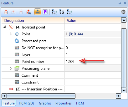
Previously, when assigning a point number to an isolated point, a feature called Assign point number was entered into the feature log of the corresponding part - at the same level as the Isolated point feature. This behaviour has changed with SP1. When creating an isolated point, the feature parameter Point number is now always entered into the feature Isolated point. If a point number is assigned, then the parameter value is adjusted accordingly. Due to this new behaviour, the deletion of point numbers is now also taken into account during feature recalculation.
Further information on this topic can be found in the news for Feature Technology.
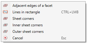
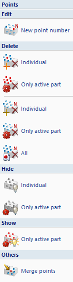
In this context, the texts in the menu 3-D Standard > Tools > Point have also been standardized.
Part attributes - Delete usage
In the Part attributes masks, fields highlighted in light yellow are fields that are locked for manual input. This applies, for example, to the Usage type. Here you only have the option of selecting a usage type from the catalogue. For several of these fields, the content can now be deleted by clicking on the  button..

Sketches
Combined Sketching Tools
The sketching tools for planar sketches and 3-D sketches have been unified and combined into one function. This means that a sketching tool with a modern look and modern functions is now also available for planar sketches. The Sketching Tool has also been significantly expanded, so that many functions that could previously be called up separately are now replaced by the new Sketching Tool.
This concerns the following sketching elements:
- Lines and polylines,
- Rectangles and Parallelograms,
- Circles and ellipses, and
- Arcs of circles and ellipses
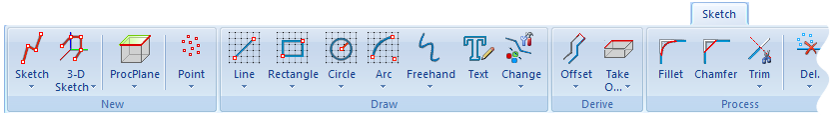
Changed Ribbon tab
The Sketching Tool is available for all drawing functions whose function icon has a grid as background.
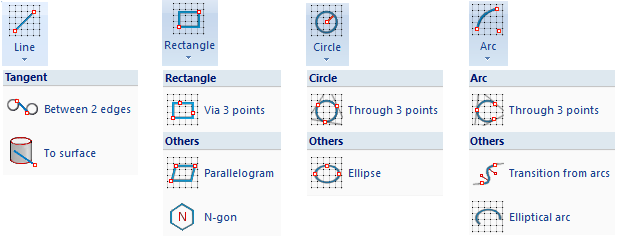
Changed menu structure
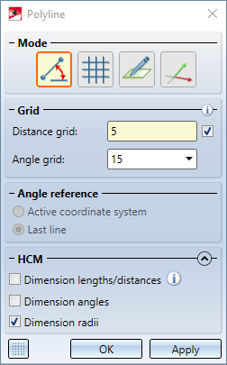
Dialogue window of the Sketching Tool for polylines
The following advantages are particularly noteworthy:
- All functions work with grids - where it makes sense.
- Individual distance grids can be used.
- Switching from drawing on a grid to free drawing can be done directly with the Sketching Tool. There is no need to start an additional function.
- Arcs can now be attached to a line directly by selecting the last point.
- New polylines within a sketch can be started directly without having to call the function again.
- HCM constraints can be set automatically directly at the drawing. This can be activated / deactivated in the dialogue window for each sketch element. While drawing sketch elements, this automatism can also be switched off for individual elements by simultaneously holding down the SHIFT key.
Display of the grid reference when sketching
The display of the grid reference when creating 2-D and 3-D sketches with the Sketching Tool can be set in the Configuration Editor at System settings > Sketches and there in the section Display of the grid reference.
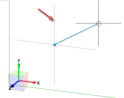
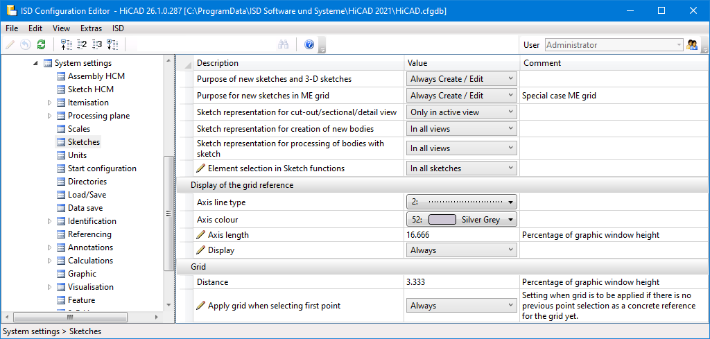
The image shows the ISD default settings.
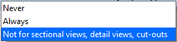
You can set the line type and colour of the axes and the axis length. At Display you can choose when the grid reference should be displayed: .
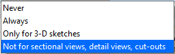
The grid of the first point and the fineness of the distance grid can also be set. The setting for the distance will take effect when HiCAD is restarted.
The following settings are possible for the first point:
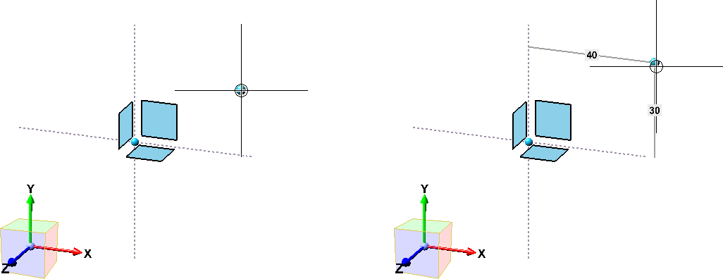
First point, without (left) and with (right) grid display
Views
Representation of the active view
In the Configuration Editor at System settings > Visualisation > Views > Frame of active view it is now possible to define for the model space as well as for the drawing sheets (sheet views) whether the active view should be highlighted by a coloured frame in the drawing.
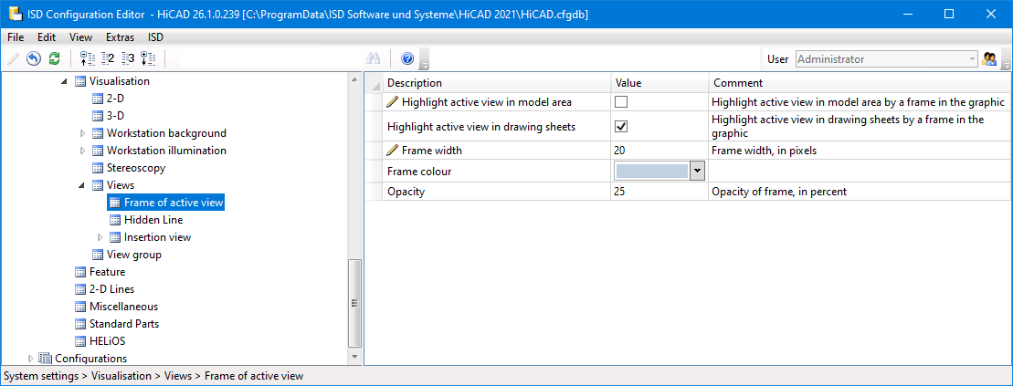
If one of the Highlight active view in... checkboxes is deactivated, the active view is displayed by a thin, dashed frame in the Special colour Marking 1. This corresponds to the display of the active view before HiCAD 2021.
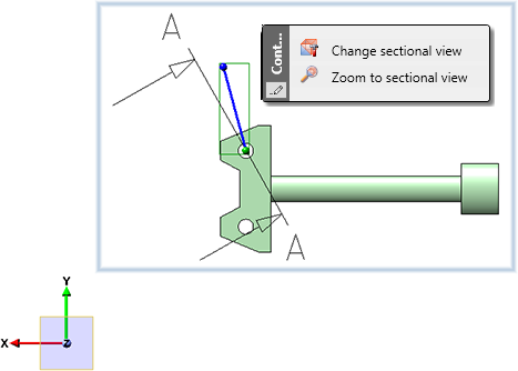
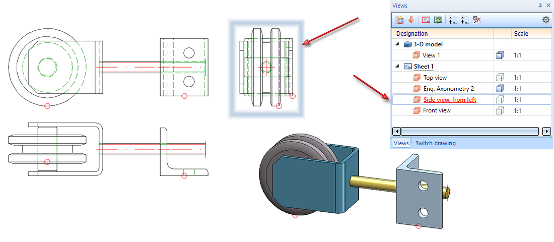
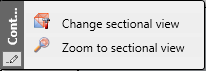
Zoom to sectional / detail view
Since HiCAD 2021, a sectional or detail view belonging to the active view can be displayed as large as possible with the functions Zoom to sectional view or Zoom to detail view. The sectional or detailed view then becomes the active view.
From SP1 onwards this also applies if the sectional view is on a different sheet than the original view.
To use the zoom functions, right-click on the annotation, designation or direction symbol in the original view of a sectional/detail view.
Change of section path in sectional view
If the viewing direction in sectional views is perpendicular to the leading cut plane, then it will be tracked from SP1 onwards when the section path is changed manually, i.e. it will also be perpendicular to the cut plane after the change. This is especially important for variable-controlled models.
However, if you have changed the viewing direction manually, then it will not be changed.
Example:
The image shows the original view with the sketch for the section path (1) and the generated sectional view (2).
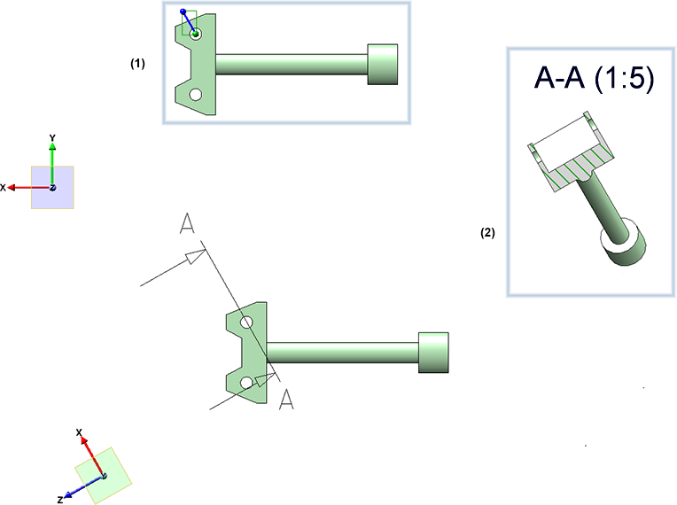
Now the section path is changed by changing the sketch.
The following image shows the result in HiCAD 2021 SP1 (1) and in HiCAD 2020 (2).
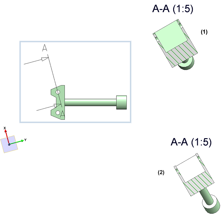
Plane position of detail view when changing the section path
For limited section views, the limiting sketch (i.e. the sketch for the detail shown) is in the leading cut plane. This is usually also the case when you have extracted a detail (with the sketch as detail section) from a section view.
If the leading cut plane now changes, then from SP1 the sketch for the detail section is adjusted so that it is again in the cut plane.
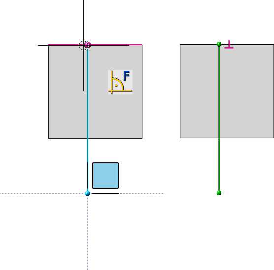
Example:
The image shows a limited sectional view (1) and the sketch plane in the detail view (2).
Now use the function Change sectional view to change the sketch (3) as shown (4). (5) shows the changed section path, (6) the sketch plane after calling the function Change detail view.
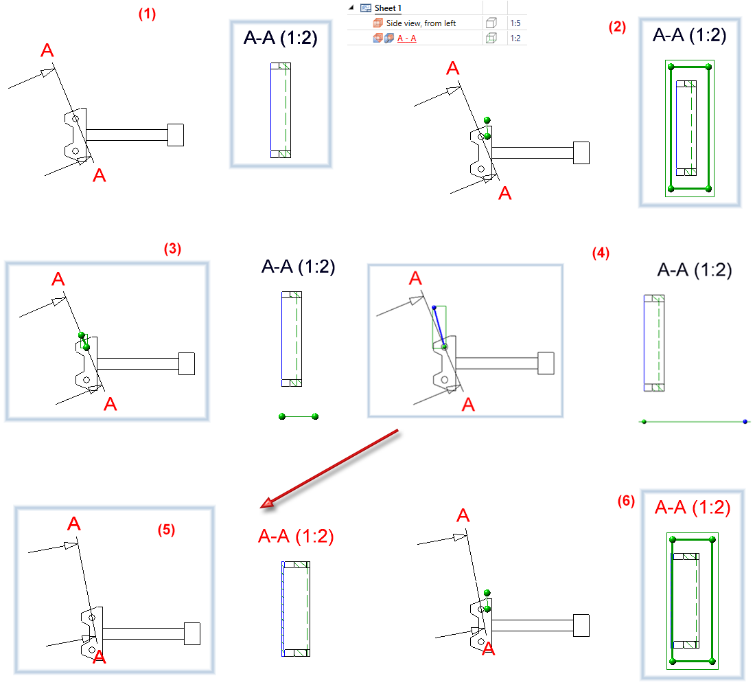
This enhancement is especially important for variable-controlled models.
Position of detail views when moving the detail
Until now the position of detail views and limited sectional views changed in an undesired way when the section in the model moved, e.g. due to the entered HCM constraints.
From SP1 onwards, the centre of gravity of the sketch or - in the case of detailed view cuboid/sphere - of the cuboid/sphere is used as a reference point and remains in this position in the drawing if possible.
This enhancement is particularly important for variable-controlled models.
Adapt bounding box size for detail views
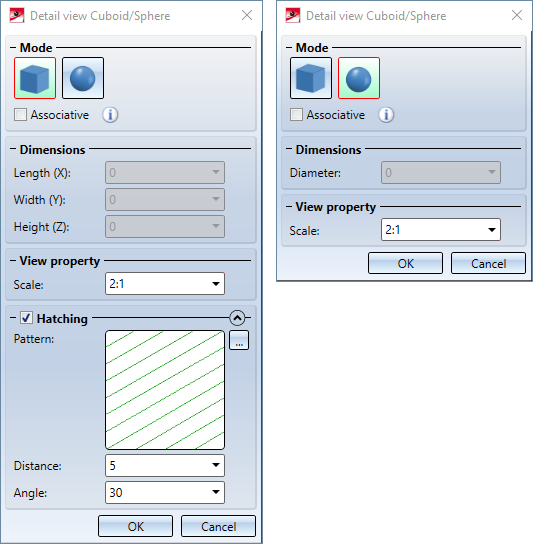
With the function Detail view, Cuboid/sphere, point symbols are displayed at the corners of the bounding box from SP1.
The box size can thus also be influenced by dragging the point symbols  . You can use the point options of the Autopilot and the Point options menu.
Dimensioning / Annotations / Text
Delete standard dimensions
With the new function Delete standard dimensions, In active sheet  all dimensions in the views of the active sheet can be deleted in one step. You can find the function at 3-D Dimensioning + Text > Delete.
Behaviour of drawing dimensions when changing the reference geometry
If the form and position of parts to which drawing dimensions refer changes, then the position of the dimensions may also change. Previously, individual dimensions were placed in relation to their first base point. When the geometry was changed, the new dimension was placed in such a way that the length of the dimension auxiliary line of the first base point was again as in the unchanged state. In many cases this led to rather unaesthetic results. As of SP1, the placement logic of the measurements has changed. The length of the shortest projection line after the change should correspond to the length of the shortest projection line before the change. The case can also occur that the shortest projection line is assumed at different base points.
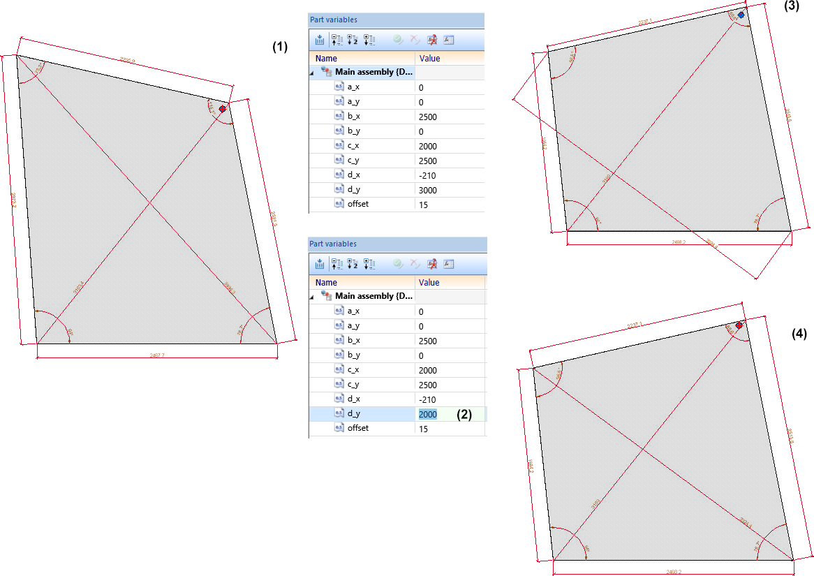
Example:
The image shows a dimensioned assembly (1) with different part variables. Now the value of one variable is changed, e.g. d_y from 3000 to 2000.
(3) shows the subsequent dimensioning in HiCAD 2020, (4) the result in HiCAD 2021 SP1.
The behaviour described above applies analogously to structural dimensions. As a rule, the smallest distance between the base point and the dimension line is also retained here, whereby all base points of the structure are to be used for this.
Attributes in annotations
Extended attribute selection in annotations
From SP1 onwards, further attributes can be used in 3-D annotation tags:
- HELiOS item attributes of the part,
- Attributes from the HELiOS document master of the part,
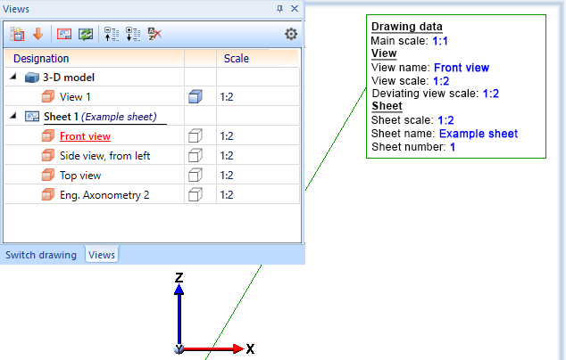
- Drawing property, e.g. main scale, name and number of the drawing sheet on which the annotation is located and name and scale of the view and
- Attributes of the HELiOS folder to which the model drawing belongs.
 Note on drawing attributes:
A different view scale only exists if the view scale and main scale are different. The sheet scale only exists if all views on the sheet have the same scale. Not relevant are sectional and detail views, views of sheet metal part developments and axonometries in workshop drawings. The sheet name only exists if a name has been assigned to the sheet.
Expanded attribute selection in annotations
Fom SP1 on, further attributes can be used in 3-D annotation tags:
- HELiOS item attributes of parts,
- Attributes from the HELiOS document masters of parts,
- Drawing information, e.g. name and number of the drawing sheet on which the annotations have been created and
- Attributes of the HELiOS folder to which the model drawing belongs
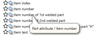
Improved attribute selection
Each attribute is marked with a symbol indicating the attribute group.
|
|
Part attribute |
HiCAD |
|
|
Attribute from the article master of the part |
HELiOS |
|
|
Attribute from the document master of the part |
HELiOS |
|
|
Item attribute of the part |
HELiOS |
|
|
Catalogue |
HiCAD |
|
|
User-defined Plant Engineering attribute |
HiCAD |
|
|
Drawing attribute |
HiCAD |
|
|
Drawing information, |
HiCAD |
|
|
Document master of the model drawing |
HELiOS |
|
|
Project attribute |
HELiOS |
|
|
Folder attribute |
HELiOS |


When you move the cursor over an attribute, a tooltip will be displayed, showing you to which attribute group the attribute belongs.
Favourites
If attributes are marked as favourites in the Annotation Editor, the list of favourites is automatically expanded when you click on the Attributes button.
HELiOS attributes in annotations
If a model drawing contains annotations with HELiOS attributes, then from SP1 these are automatically updated when the drawing is loaded. This behaviour can be switched off in the Configuration Editor at System settings > HELiOS. There you can deactivate the Update annotation tags with HELiOS attributes checkbox.
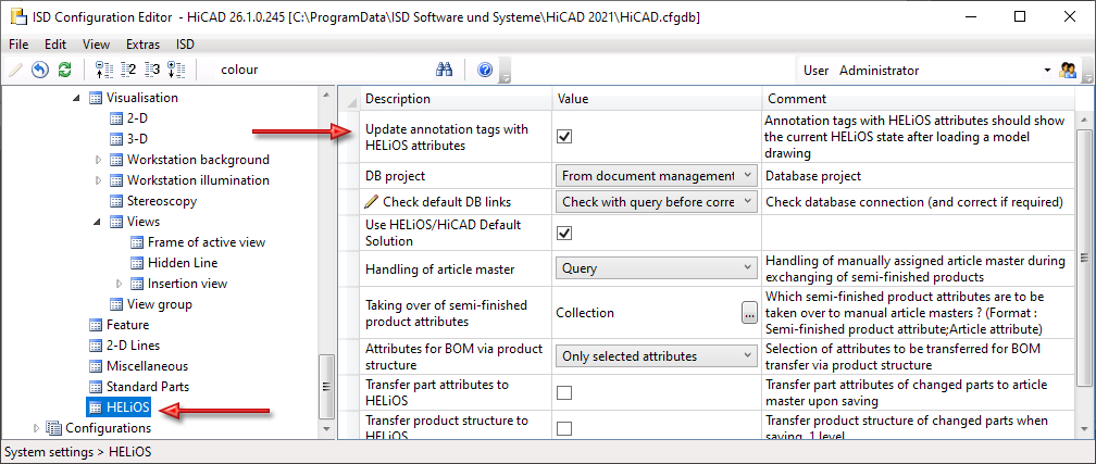
Already released drawings will not be updated!
Referencing
Product structure to HELiOS
In the Configuration Editor (ISDConfigEditor.exe), the checkbox Transfer product structure to HELiOS is available at System settings > HELiOS. If this checkbox is activated, the product structure (1 level, i.e. on the first hierarchy level) is automatically transferred to HELiOS when saving parts changed in HiCAD (with article master assignment or with BOM relevance). In this case, the Product structure to HELiOS checkbox in the Save referenced parts dialogue is active but greyed out. This means that it cannot be deactivated in the dialogue.
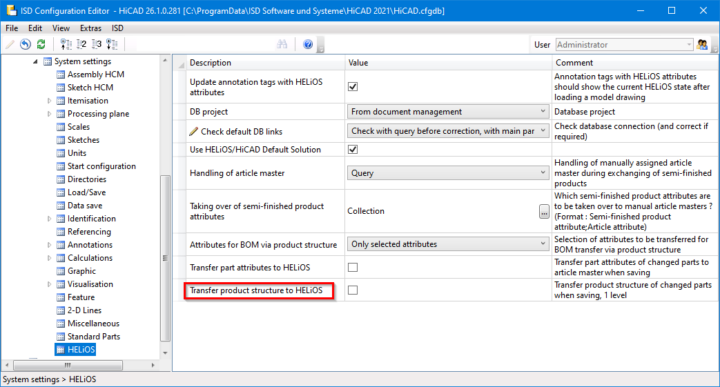
Note:
The above configuration setting is only possible if both HiCAD 2021 and HELiOS 2021 have been updated to Service Pack 1. If one of the two applications is available in a version lower than V 2601, the option is not available.
Allow part exchange in drawings
If you use HiCAD in conjunction with HELiOS, the settings for part exchange from the HELiOS Database Options on the HiCAD tab were previously taken into account when exchanging referenced parts. These settings can now be found in the Configuration Editor at System settings > Referencing in the HELiOS section.
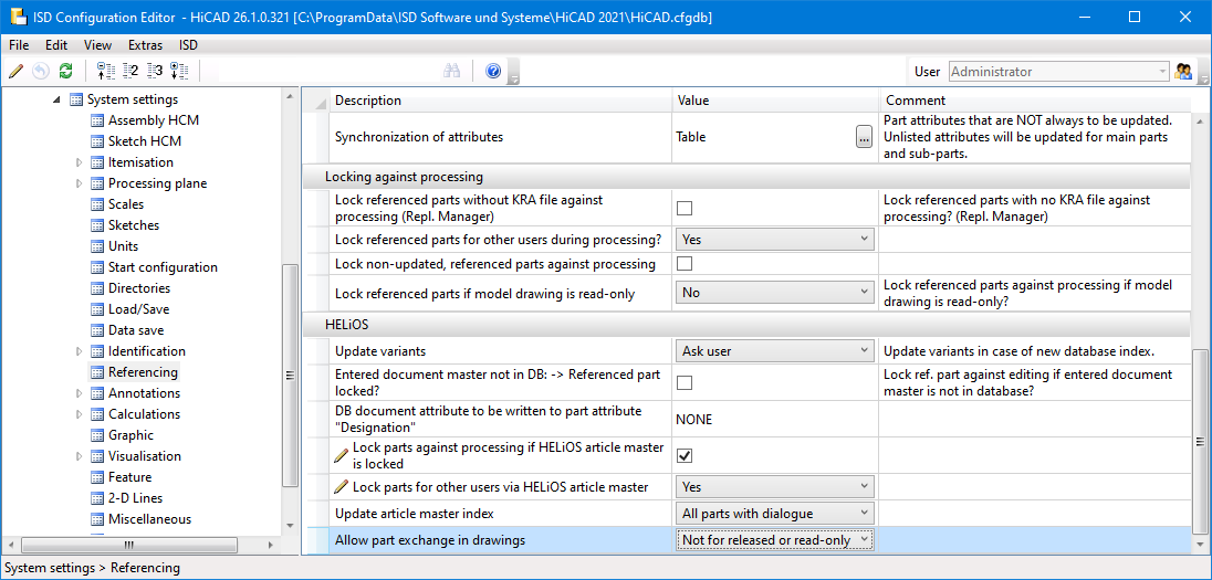
For users with a HiCAD version before 2021 SP1 (2601), the Options in HELiOS are still available.
Major Release 2021 (V 2600)
Views
Stereoscopic representation
The function Stereoscopic representation (previously available at Views > Properties > Stereo) is no longer available as of HiCAD 2021.
Representation of the active view
The active view is now represented in the model drawing by a coloured, wider view frame.
The frame display of the active view - colour, line width and transparency of the frame - can be preset in the Configuration Editor at System settings > Visualisation > Views > Frame of active view. You determine the colour by specifying the RGB values. There you can also set whether the active view should be marked or not. The image below shows the ISD default settings.
Maximum number of views and Sheet areas
As of HiCAD 2021, a maximum of 9998 Sheet areas and views can be created. The Model area is included in the number of Sheet areas.
Delete all Sheet areas
If all Sheet areas are selected when calling the Delete  function, they will be deleted without confirmation and a new Sheet 1 will be created - without views.
Change sheet names
When creating new sheets, the name Sheet n is given by default, where n is a consecutive number. With the function Change sheet name  , a sheet name can also be specified, which is then displayed in brackets behind the sheet designation in the view ICN.
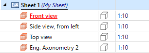
Sheet names can also be used for sheets in the production drawings created with the drawing derivation function. These are retained even when the drawing is updated.
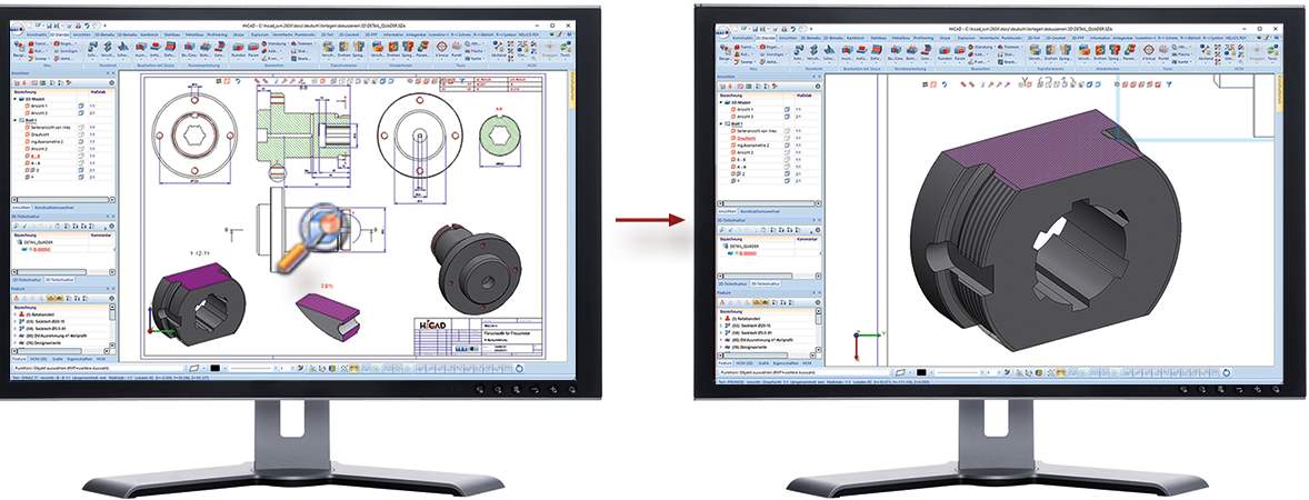
Zoom to sectional/detail view
If you right-click the annotation, the designation or the direction symbol in the original view of a sectional view and then call the
 Zoom to sectional view function, the corresponding sectional view is displayed as large as possible and activated.
Similarly, the  Zoom to detail view function zooms and activates the corresponding detail view accordingly.
Detail view, Cuboid/Sphere - Associative behaviour
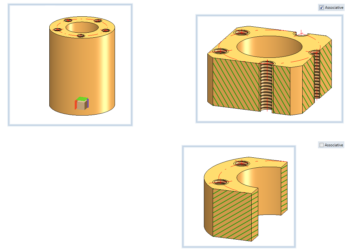
If one or more HiCAD Point options are used to define the cuboid, then the checkbox Associative can be used to define how the detail view should behave if the corresponding points are moved due to changes in the construction.
If the checkbox is active, the detail section follows the changes, it can, for example, "go along" with a moved geometry.
This is not the case if the checkbox is inactive (default setting). The detail view always shows the same spatial section, regardless of whether the original geometry is still in that position.
An example:
The image below shows the Detail view, Cuboid of a cylinder with bore and threaded holes. The centre of the cuboid is in the centre of the cylinder bore. The size of the cuboid is determined by the centre of the right-hand threaded hole.
Now the cylinder is moved to the right.
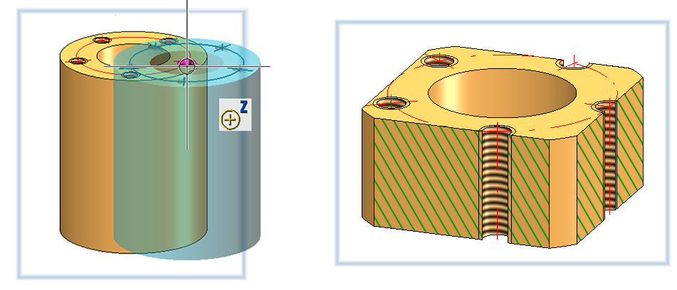
The following image shows the difference between associative and non-associative behaviour after updating the detail view.
Detail view, Cuboid/Sphere - Rotations
In addition to scaling, i.e. dragging the individual side surfaces, you now also have the option of rotating or moving the cuboid. The corresponding functions are available in the context menu after pressing the right mouse button. If rotate is selected, the cuboid can be rotated around an axis by selecting the rotation circle of the respective axis with the cursor and then rotating it dynamically with the cursor. When moving, select one of the marked points on the cuboid and drag the point to the new position.
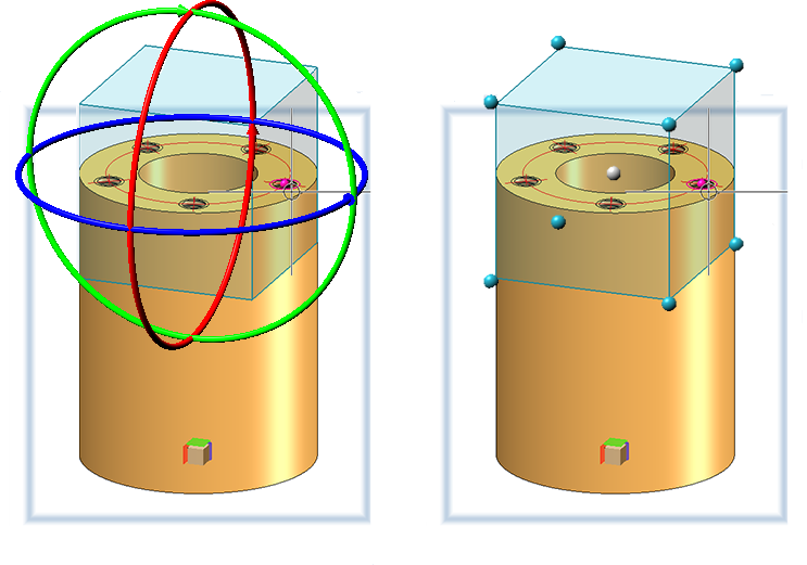
If you want to move the sphere, click on the centre point and drag the sphere to the desired position.
Discontinuation of shading type
Up to now, the shading type Flat could be used as the simplest and fastest shading method. By changing the renderer to OpenGL version 4.3, the graphics output in HiCAD is accelerated in width, which is reflected in a higher frame rate (frames/second). Viewing functions such as zooming, rotating or panning are thus significantly faster and appear even more fluid.
For this reason, the shading method Flat is no longer needed. The function Properties > Shading type  has therefore been removed from the context menu for views.
Show/Hide Parts
Up to now the functions
 Hide parts in active view and
 Show parts inactive view
could only be called up via the context menu for parts. As of HiCAD 2021, the functions are also available in the Views Ribbon tab at Parts > Hide > ... .
Process parts
Parametric cloning with external references
During designing, reference is often made to other drawing objects when inserting parts, for example when you want to fit a hole relative to the centre of a hole in another part, or cut a beam on another part. This reference between two parts is called an external reference. If the part to be cloned (copied) has feature parameters with an external reference, you can now use the checkbox Deactivate external references to specify whether the external references are to be taken into account during cloning or not. By default, the checkbox is inactive. This corresponds to the previous standard behaviour when cloning parts. If the checkbox is active, the external reference of the original is taken over for all cloned parts.
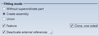
The image below shows a framework (1) with a trimmed filling rod (2) on the left. This filling rod is to be cloned (copied) by linear repetition in such a way that the framework is evenly filled with trimmed filling rods. Due to the cut, there is an external reference between the filling rod (2) and the lower framework beam. On the right you can see the result with and without the use of external references.
Divide along direction
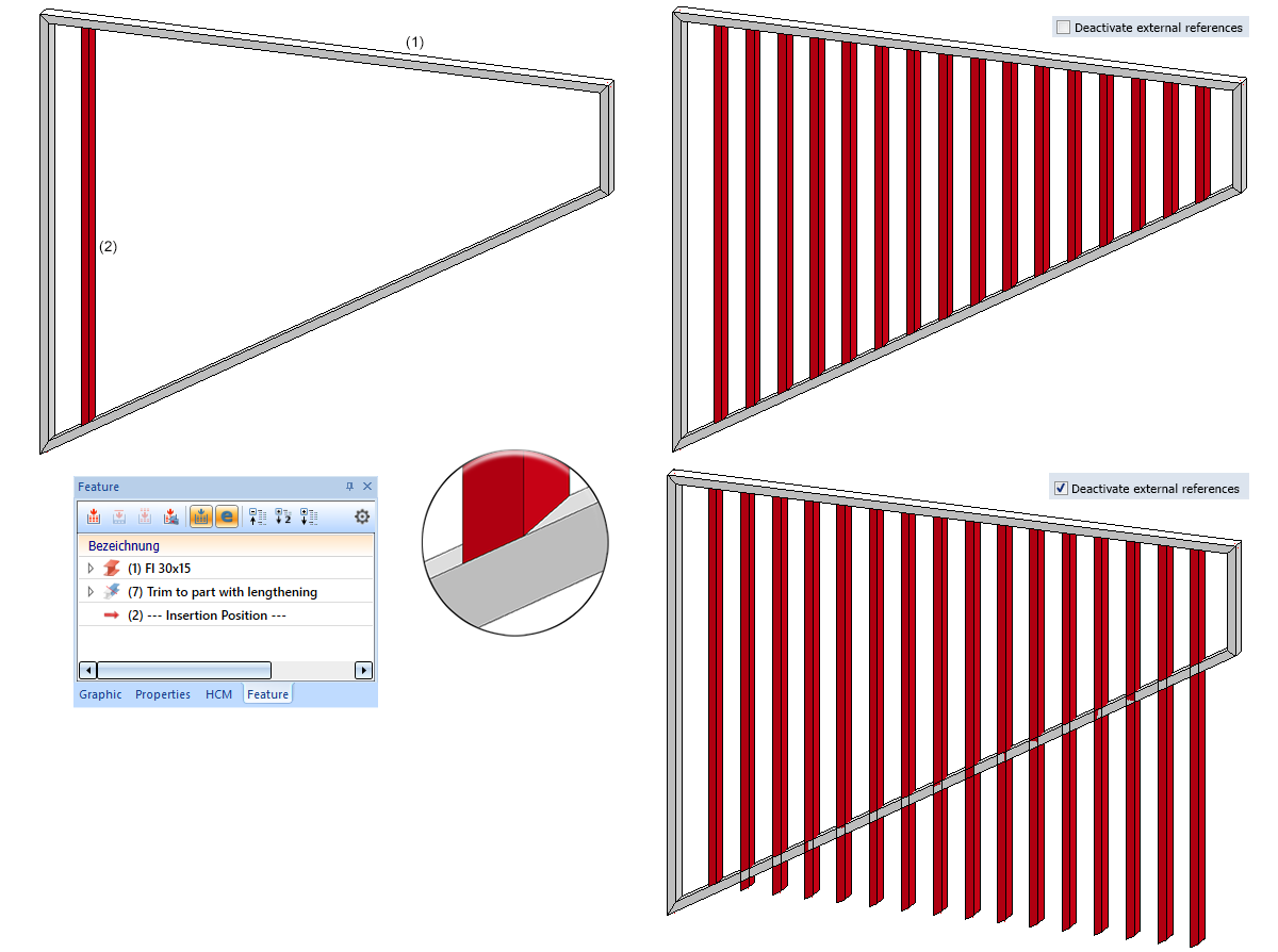
With the Divide along direction function, Sheet Metal parts can also be divided from HiCAD 2021 onwards.
- The division can now also be executed by pressing the middle mouse button instead of the OK button.
- Feature editing has been improved:
- The feature of the initial part has been renamed to Divide along direction.
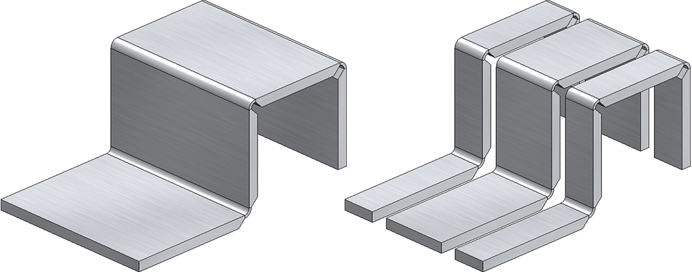
- For updating the parts after changes of the original part, the function Recalculation with updating of associated parts
 is now available directly in the toolbar of the feature window in the ICN.
- If the feature Divide along direction of the original part is deactivated, the features from division of the other segments are automatically deactivated as well.
- For dividing beams and profiles, the function Divide along direction is available in the Steel Engineering Ribbon at Lengthen > Divide, which works essentially analogous to the 3-D function Divide along direction except for the following differences:
- With the 3-D function, 3-D solids, Sheet Metal parts, beams and profiles can be divided, with the Steel Engineering function only beams and profiles.
- The 3-D function always processes the active part. The steel engineering function, on the other hand, prompts you to select the beam to be processed.
- The Steel Engineering function remains active after the division, i.e. the next beam to be divided can be selected. The beam selection is ended with the middle mouse button.
Standard Processings, Standard Parts and Boltings
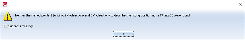
Inserting purchased/factory standard parts
Purchased/factory standard parts and moulding tools are also placed in the model drawing via the Fitting CS of the corresponding KRA file or via three isolated and named points defined in the KRA file (Point 1 for the origin, Point 2 for the X-direction, Point 3 for the Y-direction). If neither these points nor a Fitting CS are defined, the following message appears from HiCAD 2021 onwards:
Lettering with HiCAD fonts
When using the Lettering function, texts of HiCAD fonts were always displayed in italics. From HiCAD 2021 on, it is possible to specify whether these texts should be displayed in italics or not. This is determined by the Aspect ratio and the Inclination angle. When a HiCAD font is selected, a corresponding selection box is displayed in the upper toolbar of the dialogue window.
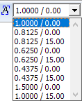
The box determines the typeface and the inclination of the text when using HiCAD fonts. If the aspect ratio is less than 1, the text is compressed. Similarly, with an aspect ratio greater than 1 the text is stretched. With an inclination of 0.00 degrees the text is displayed normally. With an inclination of 15.00 degrees the text is displayed in italics.
Geometric representation of bearings
The geometric representation of bearings has been significantly improved. Both in simple and exact representation, all ball / rolling elements are now shown. The increase in the number and position of the rolling elements also results in technically useful sectional views with improved hatching, which is opposite for the inner and outer ring.
The following figure shows the representation of a tapered roller bearing (DIN 722).
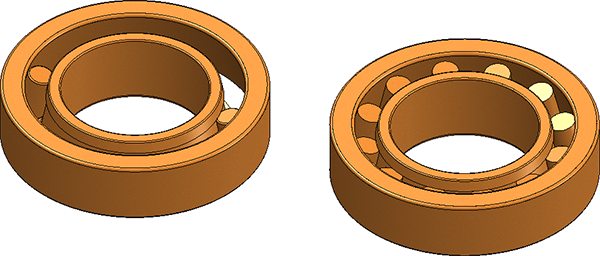
Left: Before HiCAD 2021, Right: From HiCAD 2021 onwards
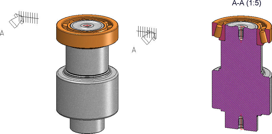
Sectional view with tapered roller bearing
Another improvement is that parametric constraints are retained when the size of the bearing is changed and do not have to be reassigned.
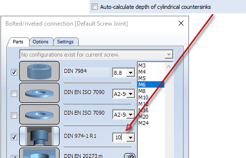
Boltings - countersink depth for cylindrical countersinks
When inserting bolted connections, the countersink depth of cylindrical countersinks can now either be entered manually or determined automatically by HiCAD. For this purpose, a corresponding checkbox has been added to the Options tab.
-
If the checkbox is inactive (default), the countersink depth is determined by the value entered on the Parts tab.
-
If the checkbox is active, then no input field for the countersink depth will be displayed on the Parts tab, but the countersink depth will be automatically calculated by HiCAD as follows:
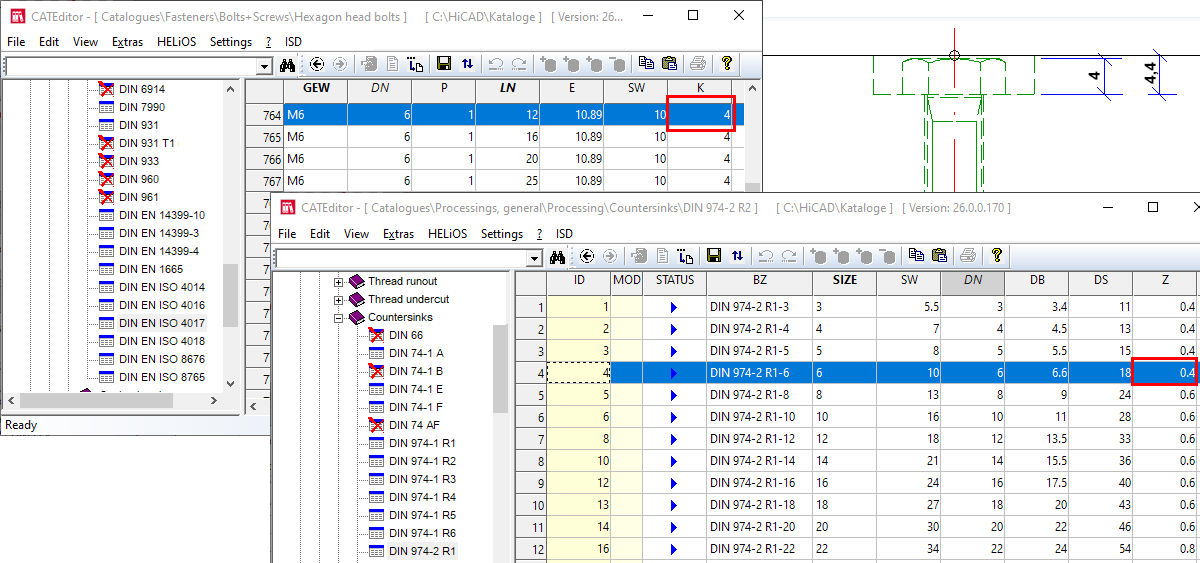
Countersink depth = Height of screw head + Value of Column Z in the table of the countersink
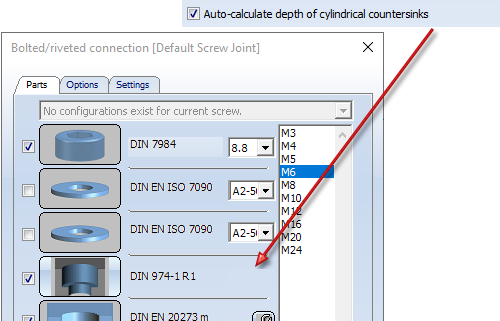
For example, if - as shown above - a screw with nominal diameter 6 is used, then the height of the screw head will be 4 and the value Z in the table of countersink DIN 974-2 R1 will be 0.4. The countersink depth will thus be 4.4.
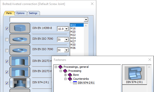
Standardised countersinks
When installing bolted connections, the corresponding standard countersink is now available for bolts according to DIN/ISO.
Dimensioning
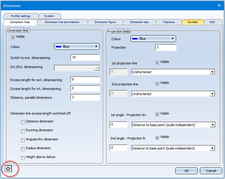
Save dimension parameters as Favourites
The parameter settings for the functions
- Set parameters for new general dimensions

- Set parameters for new parametric dimensions
 , and
, and - Set parameters for new constraint dimensions

can now be saved as favourites for a later reuse. To do this, click on the symbol in the dialogue window. Read more about managing of favourites in the HiCAD Basics Help at Manage Favourites.
Favourites are stored in the Favourites sub-folder of the folder in which the HiCAD configuration database is located. If you have installed HiCAD from the red DVD with the ISD default settings, this is the folder ProgramData\ISD Software und Systeme\HiCAD 2021. For each functional area in which you have saved favourites, a corresponding sub-folder is created in the FAVOURITES folder, For 3-D dimensioning this is the DIMENSIONING\SETTINGS folder. The favourites of the various parameter settings are saved there in further sub-folders:
|
Default |
Favourites for general dimensions
|
|
|
Parameters |
Favourites for parametric dimensions |
|
|
HCM |
Favourites for constraint dimensions |
|
More information on favourites management can be found in the Manage Favourites topic in the HiCAD Basics Help.
Change dimension parameters, Individual
The function Change dimension parameters, Individual  has been changed. After calling the function, several dimensions to be changed can now be selected. With the right mouse button the selection of the dimensions is ended and the dialogue window Dimension parameters is displayed.
The function with the same name in the context menu for dimensions remains unchanged, i.e. only the individual dimension is changed here.
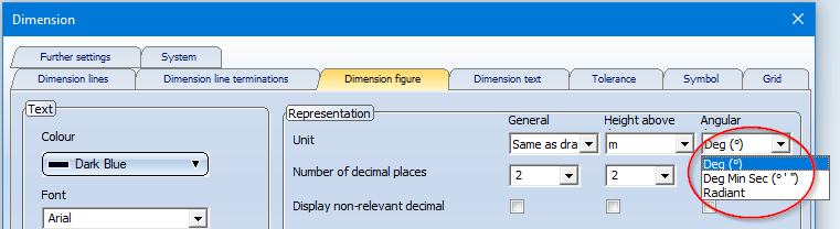
Units of measurement for angular dimensions
In the parameter settings of the functions
- Set parameters for new general dimensions
- Set parameters for new parametric dimensions , and
- Set parameters for new constraint dimensions
the unit Centesimal degree (bzw. GON) for angular dimensions is no longer available.
This also applies to the settings in the Configuration Editor at
- Drawing > Annotations > Dimensioning, 3-D > interactive dimensions,
- Drawing > Annotations > Dimensioning, 3-D > Parametric dimensions, and
- Drawing > Annotations > Dimensioning, 3-D > HCM dimensions.
Grid annotations
The 3-D grid function now inserts grid annotations on both sides of the grid.
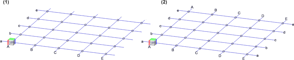
(1) up to HiCAD 2020, (2) as of HiCAD 2021
Copying internally referenced parts
To reuse internally referenced parts, you can simply copy the part. To do this, you can also use the Copy to HiCAD Clipboard and Paste from HiCAD Clipboard functions in the ICN toolbar. Please note the following: If an internally referenced part or an assembly with internally referenced parts is inserted via the HiCAD clipboard from a construction into another construction in which internally referenced identical parts to the internally referenced parts of the clipboard already exist, then HiCAD asks whether these parts are to be adapted to the version in the drawing, e.g.
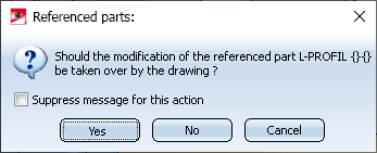
The checkbox Suppress message for this action is new here. Via this checkbox it can now be determined whether the update must be confirmed explicitly for each of the parts or not. If the checkbox is inactive (default setting), the query was made for each corresponding part - as before HiCAD 2021. For assemblies with many internally referenced parts, this can be very annoying and time-consuming.
If the checkbox is active, then a subsequent click on Yes causes the update to be carried out for all corresponding parts without further query. If No is clicked, the corresponding parts from the clipboard remain unchanged.
Only if the parts in the drawing actually deviate from the corresponding parts of the clipboard will the query be displayed again.
