Project: HiCAD Steel Engineering
"Civil Engineering functions" docking window > Steel Engineering > Connections > Front side to web/flange side > Flange > Stabilizing pipe connection (2702)
This Design Variant creates a stabilizing pipe connection of the type BESISTA between 2 beams or plates. You can choose between the following options:
When connecting beams, the stabilizing pipe connection normally brings the gusset plates with it. But you also have the possibility to attach the stabilizing pipe to plates that already exists on the beam.
Please note that the plates must be in the same plane when mounting the stabilizing pipe to plates.
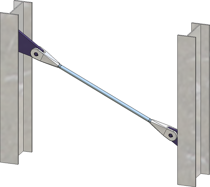
Stabilizing pipe connection Besista
Tabs
The connection is configured via settings on the following tabs:
Favourites
The settings of the dialogue can be saved as Favourites and reused at any time. To do this, click on the  symbol at the bottom left of the dialogue window to activate the context menu. You can find more information on managing favourites in the r Manage Favourites topic of HiCAD Basics Help.
Buttons
|
Preview |
When the dialogue window is open, you can use the Preview button to display a preview of the connection created with the current settings. You can also use the zoom functions to enlarge and downsize the current image detail. |
|
OK |
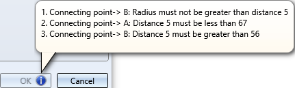
You start the generation of the connection with OK. The generation status is indicated by a progress bar in the status bar. After generation, the dialogue window is closed. If it is not possible to install the stabilizing pipe because of the entries made, this is indicated by the
|
|
Cancel |
When you click on Cancel the dialogue window is closed without generating the connection. |
![]() Please note:
Please note:

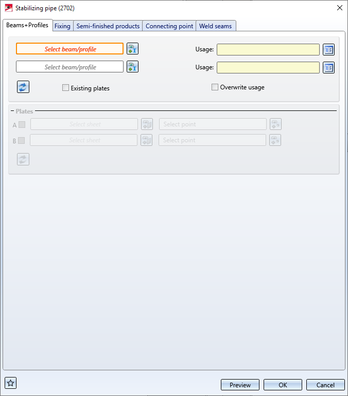
On this tab you determine which beams or plates are to be connected to each other by the cross-bracing. In the case of beams, the connection usually already includes the gusset plates for the connection. Alternatively, you can also use plates that already exist on the beam as gusset plates. This can be useful, for example, if you want to install two cross-bracings between two beams and the second cross-bracing is to be attached to the gusset plates of the first cross-bracing.
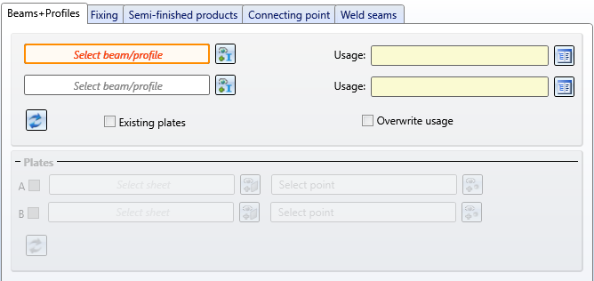
Select - if necessary by clicking on the  symbol - the desired beams. Allowed beam types are I-, L-, U- and T-beams and hollow profiles.
For each beam you can select a usage from the catalogue. If a usage is already assigned to the beams' assemblies, you can use the Overwrite usage checkbox to specify whether the usage should be retained or replaced by the usage selected on the Beams+Profiles tab.
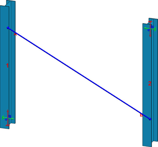
After selecting the beams, they are visualized in the model drawing - including the diagonal of the stabilizing pipe.
To restore the settings on this tab to defaults, click on the  symbol.
The connection automatically provides the gusset plates for the connection. Alternatively, existing plates on the beam can also be used as gusset plates. This can be useful, for example, if you want to install two stabilizing pipe connections between two beams and the second connection should be attached to the gusset plates of the first stabilizing pipe connection.
If the cross-bracing is to be attached to plates that already exist on the beams, you can select the corresponding plates in addition to the beams. To do this, activate the corresponding checkbox in the Plates area, select the plate and specify a point for the centre of the attachment.
Please note the following:
If you want to install the connection between plates - independent of beams - activate the Existing plates checkbox. Then activate the corresponding checkbox in the Plates area, select the plate and define a point for the centre of the bore grid for the mounting.
Please note the following:
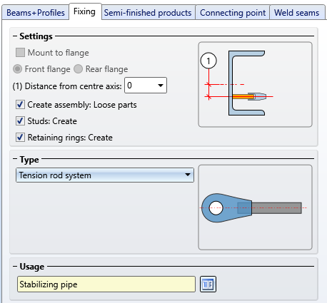
Here you determine how the connection should be attached to the beams and which Type of the connection should be created.
Mount to flange
If the connection between two beams is to be created, you can specify here whether the gusset plates are to be attached to the flange of the beams and, if so, whether the attachment is to be at the front or rear flange.
Distance from centre axis
If the attachment is not to be made to the flange, you have the option of setting the distance from the centre axis. This value determines the fitting point of the of the first plate on the beam that you identified first.
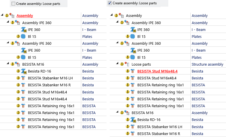
Create assembly: Loose parts
If this checkbox is active, the studs and retaining rings for fixing to the gusset plate are combined into one structure assembly called Loose parts. If this checkbox is inactive, the studs and retaining rings are assigned to the assembly of the respective tension rod system.
Studs: Create / Retaining rings: Create
Use these checkboxes to define whether studs and retaining rings are to be installed for mounting to the gusset plate.
The following types of the stabilizing pipe connection are available:
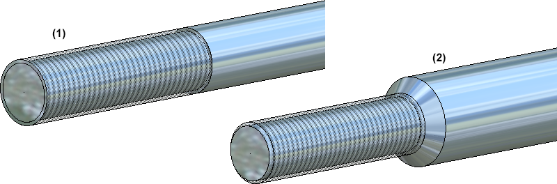
(1) Tension rod system, (2) Pressure rod system: Solid rod
A Usage can be assigned to the assembly with the tension rod system. The usage Stabilizing pipe is the default setting.
In this area you select the semi-finished products for the stabilizing pipe and the gusset plates. Which fields are active here depends on the type selected on the Fixing tab
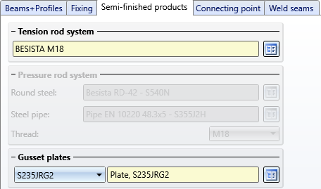
Click on the  symbol and select
directly in the corresponding standard parts catalogues. Tension rod systems can be found in the catalogue Steel Engineering > General management > BESISTA rod system, gusset plates catalogue in the catalogue Semi-finished products > Plates.
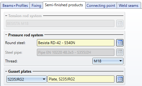
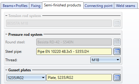
Click on the symbol and select
The round steel can be selected from the catalogue Factory standards > Factory beams > Besista, the steel pipe from the catalogue Semi-finished products > Beams+Profiles > Steel pipes, and the gusset plates from the catalogue Semi-finished products > Plates.
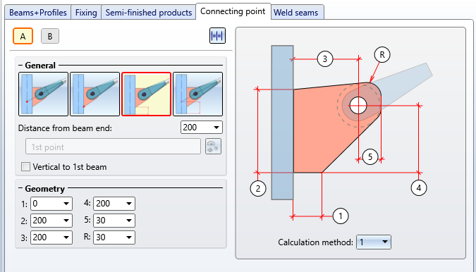
Here you define how the gusset plates are to be connected to the beams. Furthermore, the geometry of the gusset plates is defined here.

|
For the gusset plates can be determined here,
You define these settings separately for both gusset plates by clicking on the corresponding letter symbol and then make the desired settings. By clicking on the |
|||||||||||||||||||||
|
General |
By selecting one of the symbols, you determine how the position of the gusset plate is to be determined - by a point determination or a distance specification. By selecting the points you also determine the assembly affiliation. If an assembly already exists with the beam concerned, the connected beams are installed as auxiliary parts of the assembly. Otherwise a new assembly with the affected beam as main part is created and the connected plates are installed as sub-parts of this assembly. |
|||||||||||||||||||||
|
|
Point as intersection of the beam and the round steel axis of the tension rod system |
|||||||||||||||||||||
|
|
Point as plate start |
|||||||||||||||||||||
|
|
Distance Beam start - Plate start |
|||||||||||||||||||||
|
|
Distance from the start of the beam to the intersection point of the axes of the beam/round steel of the tension rod system |
|||||||||||||||||||||
|
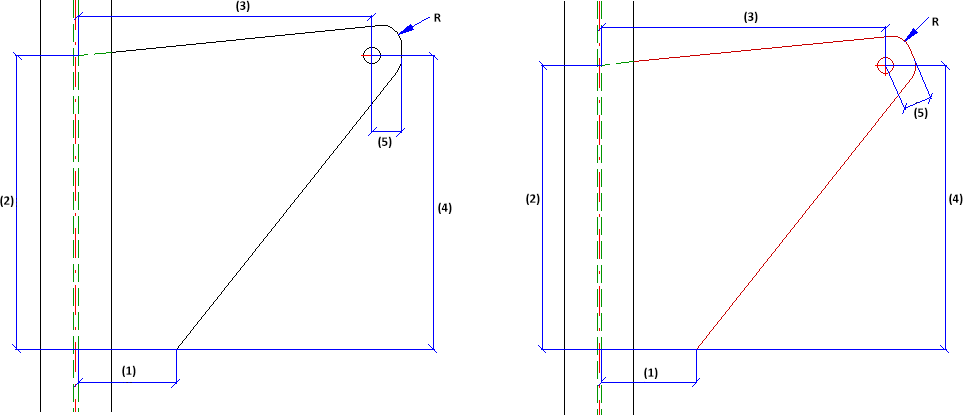
Geometry |
Here you determine the geometry of the gusset plates. Two calculation methods are available for this purpose, which you can select in the selection box below the graphic.
|
 If plates are selected on the Beams+Profiles tab, the settings and options of this tab are inactive.
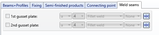
On this tab you determine which weld seams are to be created on the gusset plates.
Specify where you want to create weld seams by activating the corresponding checkboxes. For each gusset plate you can choose the type of thickness designation, the weld seam thickness, the weld seam type and the inspection category. If you want to use the same settings for the other gusset plates, click on the Equate  button.
For continuous HV and HY weld seams, enter 0 as the weld seam thickness.
If plates are selected on the Beams+Profiles tab, the settings and options of this tab are inactive.

Connections + Variants (3-D SE) • Dialogue Window for Connections (3-D SE) • The Catalogue System for Connections+Variants (3-D SE)
|
© Copyright 1994-2020, ISD Software und Systeme GmbH |
Data protection • Terms and Conditions • Cookies • Contact • Legal notes and Disclaimer
 symbol in the dialogue window. If you point to this symbol with the cursor, an explanation is displayed, e.g.: