Project: HiCAD Element installation
Example: Create Parts with Connection Parameters - Step 1
Step 1: Create variant for element installation
The topic Customer-specific Installation Elements explains in detail how to proceed to create your own installation elements. Therefore, only the basic steps will be listed here.
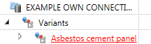
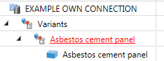
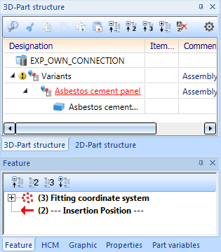
- Create an assembly called Variants. In this assembly, and create another sub-assembly called Asbestos cement panel.
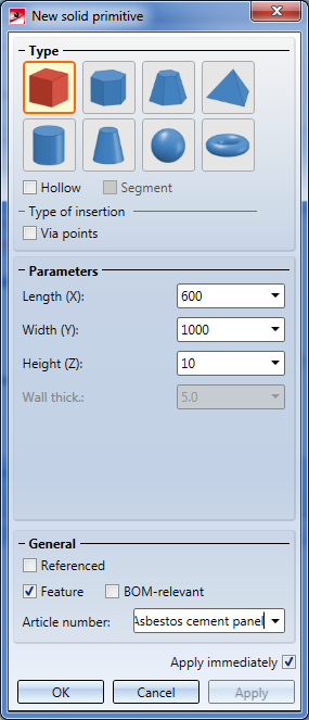
- In this assembly, create a cuboid with the 3-D Standard > Solid primitive function. In the dialogue window, enter the following values for the dimensions:
- Length (X): 600
- Width (Y): 1000
- Height (Z): 10
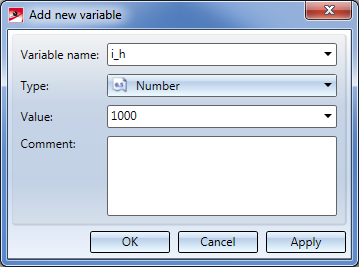
- In the ICN, right-click the Asbestos cement panel assembly and choose Properties > Part variables.
- Click the Add new variable button and create a variable called i_h, Type: Number, Value:
1000. Create another variable called i_l, Type: Number, Value:600.

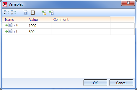
- Close the Part variables window with a click on the OK button.
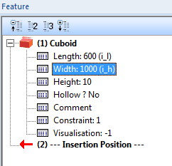
- Select the cuboid. In the Feature window of the ICN you can find the Feature log entry Cuboid. Expand this entry and double-click on the sub-entry Length: 600. In the displayed window, enter the value
i_l. Proceed likewise to asign the value i_h to the entry Width: 1000.
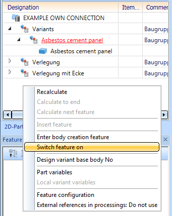
- Select the assembly Asbestos cement panel. As there is no Feature log for this assembly yet, you need to activate it: Right-click on the empty Feature window of the ICN and choose Switch feature on.
- Then, choose Drawing > Others > World CS
 > Define Fitting CS and identify, one after the other, the points at the bottom left, bottom right, top left on the upper side of the cuboid.
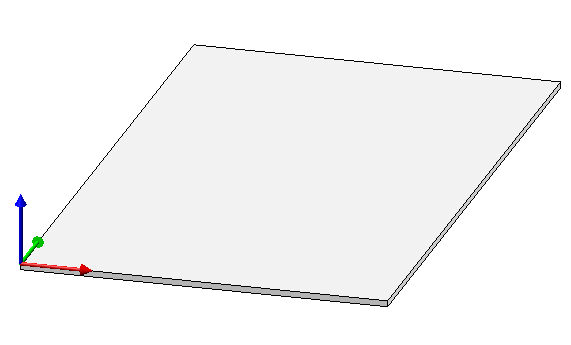
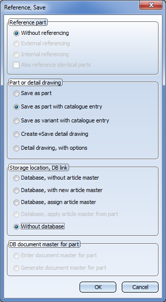
- The cuboid is now prepared for a saving to the element installation catalogue. Select the assembly Asbestos cement plate and choose the function Drawing > Save/Reference > Reference part, Save, Detail drawing. In the displayed dialogue window, choose the settings Without referencing, Save as part with catalogue entry and Without database.
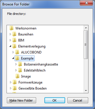
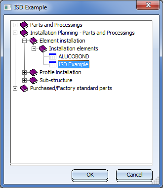
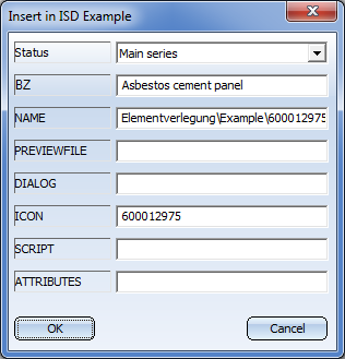
- Choose the data directory Werksnormen\Elementverlegung\Example and the catalogue Installation planning - Parts and Processings > Element installation > Installation elements > ISD Example. The settings that will then be displayed can be applied as they are; no Bitmap creation will be required here.
Next step: Create variant for sub-structure


Connection Parameters
|
© Copyright 1994-2020, ISD Software und Systeme GmbH
Version 2502 - HiCAD Element installation
Date: 27/09/2020 Language: 1033
|
> Feedback on this topic
|
• • • •