Project: HiCAD Element installation
The variants offered for Element Installation are defined in the HiCAD catalogue at Factory standards > Installation planning - Parts and Processings > Element installation > Installation elements. One distinguishes between ALUCOBOND and ISD Example elements.
Furthermore, you can also define your own, customized installation elements. Here you distinguish between:
![]() Please note:
Please note:
Installation elements can also represent doors or windows, and not just facade parts.
Rectangular installation elements
To ensure that the installation element can be automatically adjusted to the utilized sketch during element installation it needs to be parameterized. Parameterization takes places by means of variables and formulas and - if required - by assigning of HCM constraints.
In any case, the variables
must be used for the installation elements!
Polygonal installation elements
Non-rectangular elements must be parameterized via the x- and y-distances of their corner points to the origin of the Fitting CS.You need to assign the variables (i_x0,i_y0), to the first point, the variables (i_x1,i_y1) to the second point, and the variables (i_x2,i_ y2) to the third point. In the process, the order of the points will be mathematically positive, i.e. anticlockwise, e.g. like this:
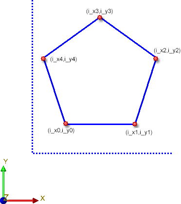
The direction for x/y corresponds to the orientation of the element installation sketch.
Variable installation elements
Installation elements can also be defined variably. For this purpose, the i_nr variable can be used. A number of corners n will be assigned to this variable. This allows an installing of this element on sketch areas with 3 to up to n corners. For instance, if the i_nr variable has been set to 5, the installation element can be placed on sketch areas with 3, 4 or 5 corners. More information about the i_nr variable can be found here.
Irrespective of whether you want to use rectangular or polygonal installation element, the definition of a so-called Fitting CS will be required, in addition to element parameterisation. The Fitting CS determines the insertion direction of a part in space. It consists of 3 special points:
If a 3-D part to which a Fitting CS has been assigned is loaded into a new model drawing, the points of the Fitting CS will be placed into the World CS. In this way the insertion direction in space will be determined.
The definition of a Fitting CS is of particular importance if the installation element is an assembly. If this assembly is saved to the Element installation catalogue while no Fitting CS is assigned to it, the Part CS will be used as Fitting CS when the part is inserted. However, this may lead to unwanted results during the installing process.
 Please note:
Not all assemblies have automatically a Feature log. For instance, this applies to assemblies that have been created with the Form assembly function, or via New > Assembly. If you assign a Fitting CS to these assemblies, no corresponding Feature log entry will be generated. To achieve this, you must assign a so-called body creation feature to the assembly. To do this, right-click on the Feature window of the assembly and select the corresponding function in the context menu. After this, the definition of the Fitting CS will be entered as a Feature here, too.
For the creation of your own installation elements the following steps are required:
The steps required for the creation of installation elements are explained by way of the following examples:
If the installation element is an assembly, all variables used must be assigned to this assembly!


Element Installation • Catalogue Editor
|
© Copyright 1994-2020, ISD Software und Systeme GmbH |
Data protection • Terms and Conditions • Cookies • Contact • Legal notes and Disclaimer