 .
. Project: HiCAD Element installation
To be able to create your own variants that a suitable for a use of the Connection function, these must be prepared accordingly.
In addition to the technical information provided in this topic you can also study a concrete example.
Both variants that are to be linked (that is, normally the elements of the element installation and the beams/profiles of the sub-structure) require a Feature log entry called Connection parameters. You create this entry by selecting Civil Engineering functions > Element installation > Connection parameters .
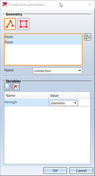
The displayed dialogue window will then query the following information:
 composite edge or a
  polygonal surface used to determine the intersection points of the connected parts.
If two parts with specified Connection parameters are linked to each other with the Connection function, a number of actions will be carried out. These will be applied to both parts.
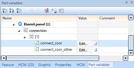
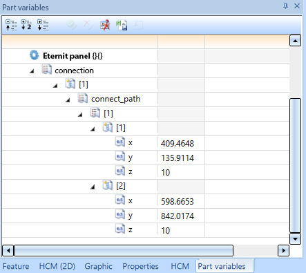
The variable created in this way can be evaluated by means of the additional Connection simulation function.
After applying changes to a part of a Connection, these changes will not automatically affect the connection. This will only happen after a Recalculation of the superordinate assembly.
To do this, select the superordinate assembly, right click in the Feature log (even if the assembly itself does not have a Feature log entry, so that the Feature log is empty!) and choose Recalculation.
To facilitate the development of own variants with connection parameters, two additional functions are available that are particularly helpful for error detection:
The function Civil Engineering functions > Element installation > Repeat connection processing  function repeats processings and sets their parameters to be able to use the parameter connect_coor correctly.
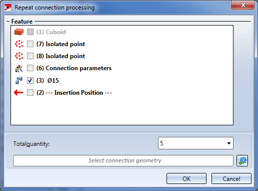
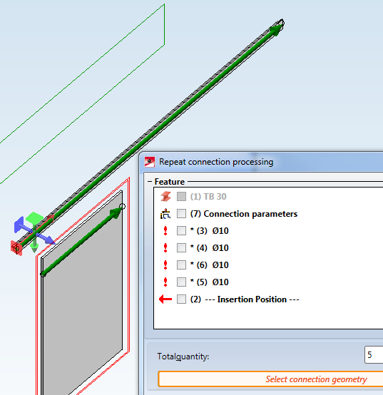
In the Repeat connection processing dialogue window you can choose the processings to be repeated by activating their checkboxes. Please note that at least one processing must be selected here. Otherwise, the error message No processing selected! will be displayed.
The Total quantity field determines how many times the processing is to be repeated. Please note that you do not specify here how often the selected processings are to be repeated, but how many processings are to be there after executing the function. If you choose the value 1, no copies will be created, but only the selected processings will be parameterized.
In the Select connection geometry field you need to choose the connection geometry that is stored in the desired Connection parameters. After clicking on the  button, all connection geometries will be highlighted by green arrows in the model drawing. Choose the desired connection geometry with a left-click.
After confirming with OK, the following steps need to be taken:
suspension. The first copy of the processing then obtains the following values: suspension[1].connect_coorlength(suspension)>=1suspension[2].connect_coorlength(suspension)>=2
The function Civil Engineering functions > Element installation > Connection simulation  performs the same steps on a variant as would be the case for a connection, but with the following differences:
In this way you can check exactly which intersection points and which resulting processing planes would be considered for a connection.
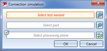
First, identify the variant to be tested. Make sure that you choose the correct part in the structure (e.g. a superordinate assembly), since HiCAD cannot determine it on its own. The part variables will then be changed on this part.
Identify the other component of the connection as its second part. This can either be a sub-structure or an element installation, but also another variant. No changes will be applied to it.
The Select processing plane option behaves the same way as in the Connection dialogue window.
After a click on the OK button, the variables will be set on the test variant, in the same way as with a "real" connection.
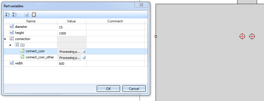
![]() Important:
Important:
When you perform this step, value inputs for the part variables of the selected part will be generated immediately. You need to delete them before saving the part to the catalogue, since otherwise a later connection would fail.
After choosing Civil Engineering functions > Element installations > Connection geometries  HiCAD will prompt you to identify a part. If this part contains connection information, the composite edges defined there will be highlighted red in the model drawing:
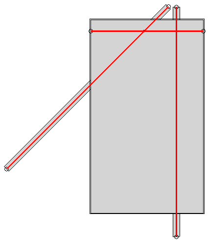
You can then select further parts to have their composite edges displayed. If you select an assembly, the composite edges of all parts contained therein will be displayed.
Press the middle mouse button to end the function.

Example: Create Parts with Connection Parameters
|
© Copyright 1994-2020, ISD Software und Systeme GmbH |
Data protection • Terms and Conditions • Cookies • Contact • Legal notes and Disclaimer