
Project: HiCAD Sheet Metal
Sheet Metal > Change length > Trim
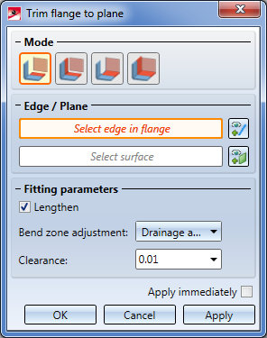
On the Change length function group of the Sheet Metal tab you find the Trim function. When you call the function, the following dialogue window that offers different trimming options will be displayed:
Proceed as follows:
Depending on the selected mode, some options may be greyed out.
If you want to identify a different flange, click on the  icon beneath Edge / Plane and identify the desired edge.
Here, too, you can select a different plane by clicking on the  icon.
icon.
 checkbox if there are flanges that do not reach up to the cut plane.
 The following processings are available for adjustment of the bend zone or milling edge zone:
|
|
Planar, shorter flange: The front surface (i.e. the abutting surface) of the bend zone is pulled back, perpendicular to the axis. |
|
|
Planar, longer flange: The front surface of the bend zone will be pulled forward, perpendicular to the axis. |
|
|
Hollow (outside): The front surface of the bend zone will connect both flanges, forming a convex front surface. |
|
|
Bulgy (inside): The front surface of the bend zone will connect both flanges, forming a concave front surface. |
|
|
Linear: The front surface of the bend zone will connect both flanges, forming a planar front surface. |
|
|
Drainage area: The front surface of the bend zone will connect both flanges in a positive locking manner, thus forming a drainage area. |
|
|
No adjustment: The front surface of the bend zone remains unchanged. |

(1) Clearance 2 mm
(2) Clearance -2 mm
If you click Apply or press the MMB, the change will also be inserted, but the window will remain open, allowing you to trim further sheets. If you select Cancel, the window will be closed, and no change will be applied. If you have activated the Apply immediately checkbox, the entered data will be applied instantly.
Subsequent changes can be made via the Feature log: Double-click on the Trim to surface feature and change the data in the displayed dialogue window.
![]() Please note:
Please note:
Incorrect inputs are indicated with the  symbol. Move the cursor over the symbol to display a short error description.
If the function cannot be executed with the entered data, a  symbol will appear on the OK button. Move the cursor over the symbol to display a short error description.

(1) Edge of the sheets to be trimmed
(2) First edge of cut plane
(3) Second edge of cut plane

|
Trim |
|
|---|---|
|
|
|
|
|
Mode: Plane, with clearance |
|
|
Mode: Individual, flush |
|
|
Mode: Plane, flush |


Overview of Functions (3-D SM) • General Notes on Sheet Processing (3-D SM)
|
© Copyright 1994-2020, ISD Software und Systeme GmbH |
Data protection • Terms and Conditions • Cookies • Contact • Legal notes and Disclaimer


