 function.
 Project: HiCAD Sheet Metal
The bend areas for sheet construction are modelled as approximated cylinder segments. During development, the individual segments are transformed to a plane and assigned additional stretching. This is to allow material elongation to be taken into account in partially plastic bending. HiCAD provides the empirical allowance methods that are used in practice.
A particular calculation method is represented by means of a system
file. These files are prepared as examples, but in practice each user
will store one or more of his own methods in this way. Before developing,
you can select the system file with the Allowance method function.
Several basic types of calculation method have been prepared. The user will choose one of these types and specify it by setting the parameters to company-specific values. The basic structure of these files, however, is the same. It is divided into comment, type ID and table.
The following allowance methods are available:
![]() Please note:
Please note:
Composite sheets (e.g. ALUCOBOND® panels) a groove is milled prior to bending. At the base of the groove, the remaining material that will be bent has a thickness of 0.8 mm. The length change resulting from the bending of the remaining material will be taken into account with a sufficient precision during the standard procedure (neutral axis in sheet centre). No explicit specification of the allowance method will be required.
Allowance methods for milling edge zones are not selectable and exert no influence.

For the creation and/or editing of the files you use the ABWEditor tool in the EXE directory of your HiCAD installation.
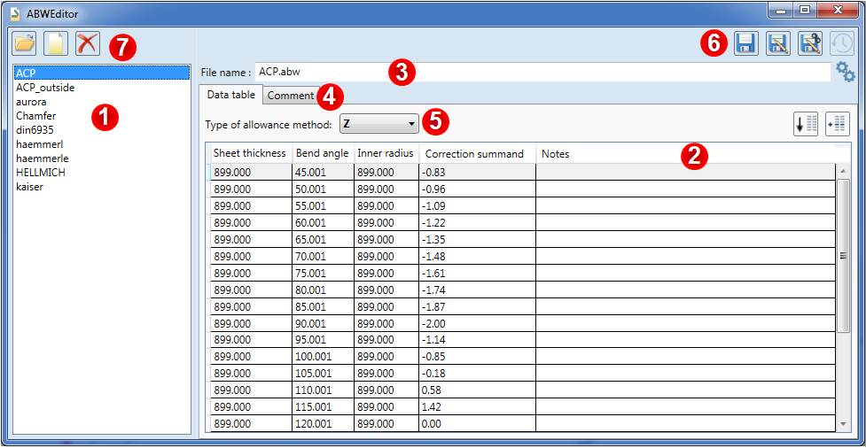
In the left column (1) of the Editor you can see the names of the ABW files that are stored in the corresponding HiCAD system directory (../MAKROABW). Only the files stored in this folder will be recognized by HiCAD as available allowance methods and offered for selection in the corresponding dialogue.
When you click on an allowance method in the list, the content of the file will be shown in tabular form on the right hand side (2) of the Editor.
This format-bound table has 4 columns and interval limits of 999.000. For method F (5) only 2 columns are relevant. For all other methods, all 4 columns are relevant.
The columns have the following meaning for the allowance method:
|
Column 1 |
Interval for included sheet thickness |
|
Column 2 |
Included bend angles |
|
Column 3 |
Included inner radiuses |
|
Column 4 |
Correction summand in mm (normally < 0) |
Click the column headers to sort the column contents in ascending or descending order. The records of an ABW file must have a particular order, which will be automatically applied upon saving. You can click the Sort data records ![]() icon to restore the correct sorting order. The Copy data record
icon to restore the correct sorting order. The Copy data record ![]() function inserts a marked table row once more. If a sorting of the table has already been done, this new row will be inserted as the next row; otherwise, it will be inserted as the last row.
function inserts a marked table row once more. If a sorting of the table has already been done, this new row will be inserted as the next row; otherwise, it will be inserted as the last row.
The displayed File name (3) can be overwritten, as well as the individual numbers in the data records. The Type of allowance method (5) can also be edited. The following types have currently been implemented:
|
F |
Factor Method, e.g. DIN6935 |
F determines the stretched length across the neutral fibre, which is corrected in the direction of the arc interior for small radii. Factor 1 means an arc length on the neutral fibre, while factor 0 reflects the arc length on the interior. |
|
Z |
The Standard Allowance Methods with External Reference Lengths, e.g. Heuschen, also Dubbel |
Z is the most frequently used method. The reference lengths for an obtuse angle are the imaginary intersection points of the sides on the flange exterior; in the case of acute angles, the reference dimension is formed via the tangent perpendicular to the dimension direction. This corresponds to the practical measurement of a workpiece using the calliper gauge. The stretched length is then the sum of the lengths determined in this way plus the allowance values per bend. The values in the table for inner radius, sheet thickness and bend angle are to be interpreted in such a way that the shortening value will be used up to this value, and will then jump to the next higher value: For example, if you have defined an allowance of 5 for an angle of up to 45.01°, and an allowance of 10 for an angle of up to 90.01°, the allowance of 10 will be used for an angle of 46°. |
|
I |
A Modified Allowance Method with Internal Reference Lengths, e.g. Kaiser |
I is similar to Z, the difference being that it is not the exterior, but the interiors of the sides that define the reference lengths. The practical significance of this method is that the user often sets all allowances to zero and obtains a simple method with acceptable calculation results for appropriate bend radii. |
|
H |
A Modified Allowance Method with Interpolation, e.g. Haemmerle |
H is similar to Z, with two modifications: First, the intersection points of the sides bound the reference line here even for angles above 90 degrees. Second, the allowance value is interpolated linearly in the interval of the angles. |
|
|
Polyhedral Developments |
The above explanations apply only to genuine sheet developments, but not to polyhedral developments. In these cases, only the existing surfaces are transformed to the plane if INT/thickness = 1000. If a thickness <1000 is specified, the stretched length resulting from the geometric middle of the specified imaginary thickness is shortened. |
The Comment (4) can be edited on the second tab of the dialogue.
The comment in the ABW files that are supplied with HiCAD consists of a description of the method and the meaning of the individual columns.
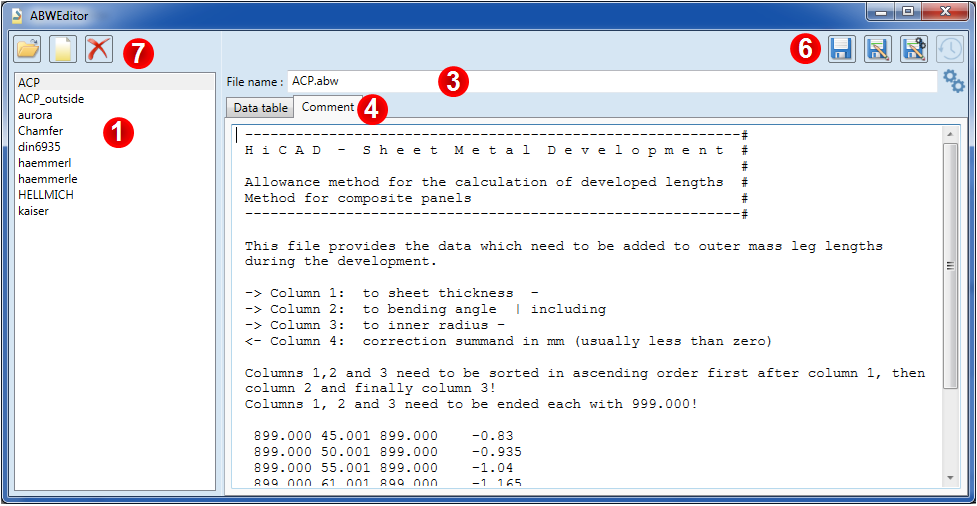
The two cogwheels ![]() next to the file name indicate that this is a system file, i.e. an ABW file that is stored in the HiCAD system directory.
next to the file name indicate that this is a system file, i.e. an ABW file that is stored in the HiCAD system directory.
If you want to load a different file (e.g. by clicking a different system file in the list or by creating a new file) you will be asked whether you want to save the changes to the current file.
In the top right corner of the Editor (6) you can find the following icons:
|
|
Save |
Use this function to save the current file to its default storage location. |
|
|
Save as... |
Use this function to save the current file to a storage location of your choice. |
|
|
Save as system file |
Use this function to save the file as a system file. This function is particularly relevant for files the storage location of which is not the system folder for ABW files, or for new files. |
|
|
Restore |
If you modify a system file and save it with its current file name, the ABWEditor will create a copy of the original file in the background. This function will then be active, i.e. not greyed out. You can then use this function to restore the original version of the file. |
With the help of the icons (7) at the top left you can manage the ABW files:
|
|
Open file |
Use this function to open an ABW file which is not located in the HiCAD system folder (../MAKROABW). |
|
|
New file |
This function creates a new, user-speific ABW file. |
|
|
Delete file |
This function deletes the current ABW file after a security prompt. |
If you want to create company-specific allowance methods it is recommended to modify existing files and save them as system files.
|
DIN6935.dat |
This file contains the factors for calculating the length change for developments according to DIN 6935.
|
|
Aurora.dat |
This file contains the values which are added to the external dimensions of the leg lengths during development. This allowance method is used at the company AURORA. |
|
Kaiser.dat |
This file contains the values which are added to the internal dimensions of the leg lengths during development. This allowance method is used at the company KAISER. |
The CHAMFER allowance method has been developed to match the requirements of the Puzzle piece Design Variant.
Before insertion of the variant, the CHAMFER allowance method must be selected for the Sheet Metal part. Proceed as follows:
 .
. With allowance checkbox to ensure that the allowance method will be considered.
Aluminium composite panels can, for instance, consist of two 0,5 mm aluminium cover sheets with a mineral core. In HiCAD the plate is represented simplified as a one-layer sheet. Since the weight calculation is done based on a homogeneous material, an own material is assigned to the panel.
For simple Aluminium Composite Panel blanks with bend zones (i.e. no modelled milling edge zones; these will only be available from Version 2300 onwards), the approximative allowance methods ACP amd ACP_outside are available. Developments and milling dimensions are derived from the 3-D drawing dimensions. Per edge, the corresponding linear dimension will be subtracted from the final dimension. The sum of the milling dimensions equals the blank dimensions.
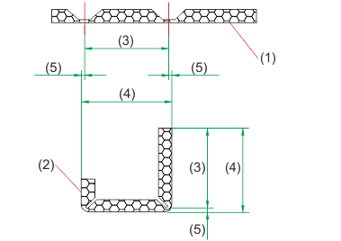
(1) Section through blank for bending simulation
(2) Section through the sheet metal part of an aluminium composite panel
(3) Milling dimension
(4) Final dimension
(5) Subtracted linear dimension per edge
If the bend zones for the composite panels are created in the standard mode, they will have a cylindrical shape as shown in the image below(8). In contrast, if the milling edge mode is used for construction, grooves will be milled along the bend zones before the bending takes place. The result will be one aluminium top sheet, as shown in the image below (6,7). To achieve a geometrical length adjustment of the modelled sheets with cylindrical bend zones on the produced real sheets with milled foldings you can use the files ACP.ABW and ACP_OUTSIDE.ABW. For bend zones with inside millings (6), use the allowance method ACP, for bend zones with outside millings (7), use the allowance method ACP_OUTSIDE.
If the sheets are constructed in the milling edge mode, the model will contain the milled bend zones. A length correction will not be necessary. No allowance method can be selected. Eine Längenkorrektur ist nicht notwendig. Es kann kein Zuschlagverfahren gewählt werden.
Bend radius (BRAD): 0.01 (Standard, for inside millings)
Bend radius, milled outside (BRAD_OUT): 1.50 (Exception, for outside millings)
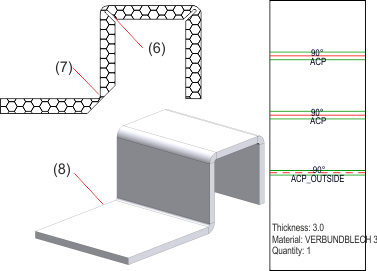
(6) Inside milling
(7) Outside milling
(8) Composite panel with bend zone

New/Change/New/Show Allowance Method • Blank Parameters
|
© Copyright 1994-2020, ISD Software und Systeme GmbH |
Data protection • Terms and Conditions • Cookies • Contact • Legal notes and Disclaimer
