Coordinate System Display
Drawing > Others > Extras  > Settings, permanent > CS display
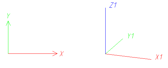
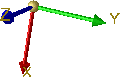
A sketch of the coordinate system can be shown as an orientation aid in the drawing. The x-axis is displayed in red, the y-axis in green and the z-axis in blue (predefined by ISD). In 3-D coordinate systems, the index of the coordinates indicates the number of the view additionally.
The size of this representation can be changed by means of the  CS displayfunction. Furthermore, you can use this function to specify in which views the coordinate system is to be displayed.
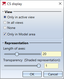
Specify via the radio buttons under View whether the coordinate system is to be displayed in all views or only in the active view. Specify whether this setting is to apply only to the Model area or to the Model and sheet area by activating or deactivating the Only in Model area checkbox . If the checkbox is activated, no coordinate systems will be displayed in the Sheet area (irrespective of the chosen radio button).
Parallel to the dialog window, a preview of the coordinate display is shown in the drawing. This preview is adjusted automatically when changing the settings under Representation. Here you can use the sliders to define the length of the coordinate axes and thus the size of the coordinate system display. Furthermore, you can define the degree of transparency for the shaded representation of the coordinate system representation. This display mode is used, for example, when working with sketches.
 Please note:
- The coordinate system display will be saved when you close HiCAD. This means that if the display is active when HiCAD is closed, it will still be active when HiCAD is started the next time.
- The colours of the coordinate system axes can be changed via the Colour Editor
 (Drawing > Others > Colour Editor). The colours for the axes can be chosen from the list on the Special colours tab.
- Part and fitting coordinate systems can also be displayed spatially in 3-D directly on the part. . For this purpose, the corresponding functions are available in the Visualisation toolbar at the bottom of the HiCAD user interface:
 Part Coordinate System on/off or
 Fitting Coordinate System on/off
zur Verfügung. Alternatively you can use either the F8 key or SHIFT+F8 verwenden.
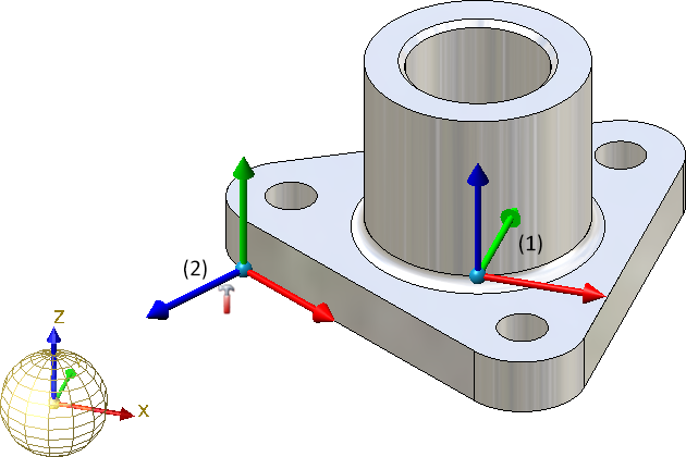
Image with a 3-D symbol of the World CS and plastic display of the Part CS (1) and the Fitting CS (2)
Furthermore, the orientation of a part, which you have defined with the Part orientation function in the context menu for parts or the profile orientation can be shown/hidden. To do so, click on the symbol
 Profile orientation or part orientation of active 3-D part.
Alternatively use the F6 key. This is only possible if the setting Switch on/off with F6 keyunder System settings > Visualisation > Show alignment of active 3-D part in drawing or System settings > Visualisation > Indicate orientation of active Steel Engineering beam in the Configuration Management has been activated.
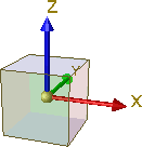
3-D Symbol of Coordinate systems
In 3-D drawings, the F3 key can also be used to show or hide a 3-D symbol of the active coordinate system. A distinction is made between world, part and local coordinate systems, for example
|
Coordinate System |
Example |
|
World Coordinate System |
|
|
Part Coordinate System |
|
|
Active / local Coordinate system |
|
 or
or 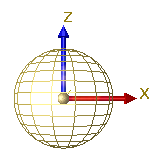
 or
or 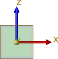
The CS display function does not refer to this coordinate system that can be hidden and shown via F3, but to the coordinate system that is displayed by default in the origin (0,0,0) of each view.
Tip:The symbol is displayed at the bottom left of the drawing area by default. You can move the symbol to any position with the CTRL+K key.
If you do not want to display any 3-D coordinate system, this can be pre-set permanently in the Configuration Editor: Choose System settings > Visualisation and deactivate the Show 3-D coordinate system checkbox.

