Plant Engineering > Pipeline Tools > Change  > Change route
The dynamic route change is now supported by a grid. This can be useful if you want to move the connecting point of a pipe by a defined value in the direction of a connection that does not run along one of the axes of the currently active coordinate systems.
The origin of the grid will always lie in the point to be moved in the process. The orientation will be selected in such a way that one of the axes of the grid runs in connection direction, and a second axis lies in the XY-plane of the active coordinate system.
The grid is represented by dotted auxiliary lines, on which the current grid spacing is visualized by means of small spheres.
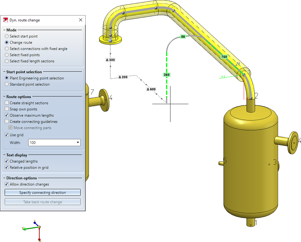
If the Relative position in grid checkbox beneath Text display has been activated in the dialogue window, the distance to the start point will be written, along the grid axes, to the auxiliary lines. To distinguish such distances from the texts with the changed lengths, they will be preceded by a capital Δ (Delta).
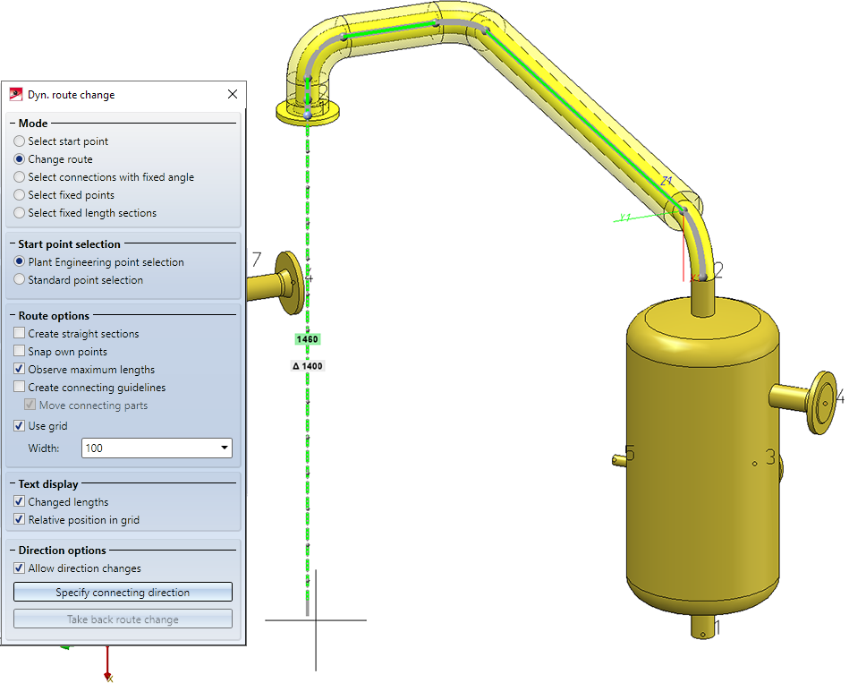
This display is particularly useful if a length change runs along a grid axis. In the image below, for instance, the short straight pipe at the end of the pipeline is lengthened in downward direction. The new length of the pipe will be 1460, while the end point of the pipeline will be moved downwards by 1400 units:
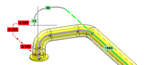
Immediately below the Use grid checkbox you can specify the incremental width (spacing) of the grid. Please note that you can also pick the grid spacing from the drawing when you have chosen Pick distance from the context menu of the input box. If the selected grid point cannot be reached with the route change, the auxiliary grid lines and the text boxes will be highlighted in red:
![]() Please note:
Please note:
- While the grid is active, you can, of course, still snap the target point of the in the drawing. In this case the grid will be automatically hidden.
- The dropping on a grid point takes place by pressing the middle mouse button, i.e. the behaviour corresponds to the "free" dropping without grid. This prevents an accidental, unwanted dropping on a grid point when you actually wanted to select a connecting point, as the dropping at connecting points is still carried out with a left-click.

