Annotation, Change Settings
3-D Dimensioning + Text > Text > Leader  > Settings - Change
You use this function to define the settings for part annotations.
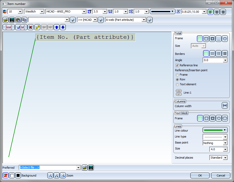
The dialogue window is composed of the following areas:
- Text blocks and text elements of an annotation
- Define representation of text blocks
- Define representation of annotations
- Define representation of leader lines
- Load and save settings
The following buttons are also available:
|
OK |
The current settings are used as default settings for subsequently created annotation texts. |
|
Cancel |
The function is ended without applying the current settings. |
|
|
The background of the text input area is temporarily switched. This can be useful, for example, if the selected font colour is difficult to read on the current background. |
|
|
The zoom functions allow you to enlarge or downsize the text displayed in the input window. |


![]() The default settings for Font, Colour and Line type of annotations as well as the distance between the text lines are determined in the POS3DPARNEU.DAT file in the
SYS directory. However, you can use the Set font function to customise the parameters of the entire annotation or individual lines of the annotation.
The default settings for Font, Colour and Line type of annotations as well as the distance between the text lines are determined in the POS3DPARNEU.DAT file in the
SYS directory. However, you can use the Set font function to customise the parameters of the entire annotation or individual lines of the annotation.

Text blocks and text elements of an annotation
An annotation is composed of different text blocks, each of which can consist of different text elements.
These can be attributes, special characters or any alphanumeric text.
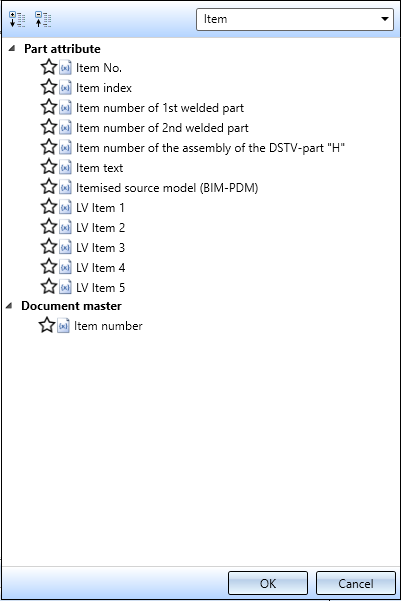
To insert an attribute, click on the Attribute ... button and select the desired attribute from the selection list. The following attributes are available for selection:
- HiCAD Part and Design Attributes
- HELiOS Article master, document master and project attributes
The selection list can be expanded, collapsed and searched for specific entries.
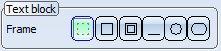
The selected annotation is displayed in the preview window. Each text block is marked by a plastic border, the active text block by a black one. Part attributes within a text block are displayed in curly brackets.
Please note that a text block can consist of several text elements.
Example of a text block:
You can use tab stops (besides the selection of HiCAD fonts) to apply a tabular alignment to text blocks of an annotation. To do this, just place the cursor at the required position of the text and press the TAB STOP key  on your keyboard.
Example of annotations with tabular alignment:
In this context please also note that you can assign horizontal and vertical dividing lines to texts which have been separated with tab stops. This allows the creation of complete tabular annotations:
Tables can be copied from or into from Excel via the Clipboard. In this context please also note the information on multiple text selection.
Assign text element
To assign text elements to a text block, place the cursor in the required text block. You can now enter normal texts directly via the keyboard. In addition, you can load text from a file, paste texts from the clipboard or copy them to the clipboard.
- Load text from file

Use this function to load texts existing in particular files. Possible are:
Text files (*.rtf, *.txt, *.dat),
Formatted text (*.rtf),
Comma-separated values text files (*.csv).
If you load texts from formatted RTF files, you can either take over the font of the original text, or use a font of the Text Editor. Here, even different formattings within a line will be considered, except for subscripted and superscripted text. In HiCAD, text height and colour have another meaning than in text processing programs and will therefore not be taken over. Please also note that for 3-D texts only the first line of the file will be taken over.
You can also take over indents, tab stops, bullet lists and numbered lists of original texts. Texts that have been separated by tab stops will be arranged in columns when they are taken over. It can therefore make sense to replace the tab stops by blank spaces. You can specify the settings for the taking over of texts in the Apply formatting dialogue window.
No formatting will be taken over from CSV files. If you copy and paste them from Excel, fonts will be considered as well.
- Save text

Use this function to save texts for a later re-use -either as text file (.TXT, .DAT) or as comma-separated CSV file.
- Paste text from clipboard

Use this function to insert texts from the clipboard. If the clipboard contains a text which has been copied to it with the text Editor, the complete HiCAD text formatting (colour, font, text height, italic, bold, line spacing etc.) is taken over. When inserting texts from other Windows applications, you can either take over the font of the original text, or use a font of the Text Editor. Colour and text height will not be taken over. You can also take over indents, tab stops, bullet lists and numbered lists of original texts. Texts that have been separated by tab stops will be arranged in columns when they are taken over. It can therefore make sense to replace the tab stops by blank spaces. As with the loading of texts from RTF files, you can specify the settings for the taking over of texts in the Apply formatting dialogue window.
Example
In the example below a WORD text (1) has been inserted in the Annotation Editor (2) via Copy & Paste. The tab stops have been simulated by blank spaces. (3) shows the corresponding annotation in HiCAD.
- Copy text from clipboard

The currently selected text is copied to the clipboard. When copying texts from the clipboard to other Windows applications, HiCAD fonts are copied as Courier fonts.
To
copy the text from a list box, select the desired entry and then copy
it using the  button. If a text element that exists in
the text block is highlighted, it is replaced. If, on the other hand, the cursor
is merely positioned in the text block without a text element being highlighted, the new text element is inserted
at the current cursor position.
button. If a text element that exists in
the text block is highlighted, it is replaced. If, on the other hand, the cursor
is merely positioned in the text block without a text element being highlighted, the new text element is inserted
at the current cursor position.
Insert/Delete/Move Text Block
The following functions are available for the processing of text blocks:
|
|
inserts a new text block (behind the active one) |
|
|
inserts a new text block in a new line |
|
|
deletes the active text block |
|
|
marks all text fields. In this way you can, for example, assign a particular colour or a particular font to all texts in one step. |
|
|
moves the active text block to the right |
|
|
moves the active text block one line up |
|
|
moves the active text block one line down |
|
|
moves the active text block to the left |


In addition, you can use the following keyboard functions:
|
Return, Enter
|
Line break, with a new field being created |
|
DEL |
Delete text / tab stop |
|
Backspace |
Delete text / tab stop |
|
Curso-keys |
Moving throughout the text blocks |
|
CTRL+C |
Copy marked text to the clipboard |
|
CTRL+V |
Paste text from the clipboard |
|
SHIFT+LMB |
Marks all text input fields between the active input field and a selected input field. Activate the input field for the start of the marking, press SHIFT+LMB and select the input field for the end of the marking. |
![]() Please note:
Please note:
- If you want to use attributes of the superordinate part when annotating a part, you can precede the attribute with the string %U. Multiple use of the letter U is also possible, in order to use the attributes of parts which are located higher in the structure, e.g. %U{item number} or %UU{item number}.
- The usage attributes from the product structure, too, can be displayed in 3-D annotations. To do this, enter the text %DBVA(ATTRIBUTNAME). Please note that in case of any changes, the annotation tags will not be updated automatically.
Representation of text blocks
You can define properties such as font, encoding (available character set), text height, line spacing, text colour and aspect ratio/inclination to each text block of a annotation.

A width factor that changes the horizontal extension of the text can additionally be specified for HiCAD fonts. The default value is 1.0. If the width factor is less than 1, the text is compressed horizontally. If the width factor is greater than 1, the text is stretched horizontally.
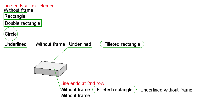
In addition to the text properties, you can also assign a frame to each text block. To do this, use the buttons in the Frame toolbar in the Text block field.
Each text block can be shown with or without a frame or underlined. Possible frames are rectangles, rectangles with double lines, filleted rectangles or circles.
![]() Please note:
Please note:
- The character set determines which fonts will be offered for selection, e.g. if you choose "Chinese", only fonts that support Chinese characters can be selected from the list box.
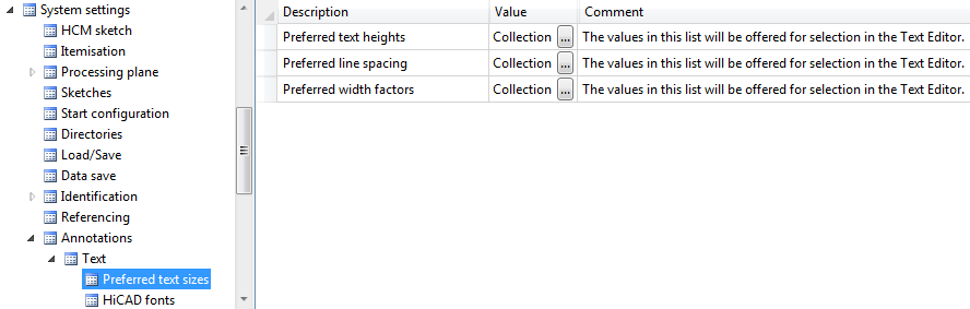
- In the combo boxes for text height, line spacing and width factor, manual inputs are also possible. Furthermore you can change or expand the values shown in the boxes. To do this, edit the corresponding collection box in the Configuration Editor at System settings > Annotations > Text > Preferred text sizes.
- The frame representation options Circle and Filleted rectangle barely differ from each other. However, the circular frame around texts usually takes a lot of space. You should therefore preferably use - most notably for texts consisting of many text elements - the Filleted rectangle frame type.
- For annotation tags with circular frame (internal) the connection point should be changed in such a way that the line points to the centre.
-
In older HiCAD versions (before HiCAD 2018 SP2) the underlining of text blocks will be ignored. Although the underlining will still be visible when loading the model drawing, and they can also be printed. But after updating the annotation the corresponding text blocks will be shown without frames.
Representation of annotations
In the Total field, you define the display of the entire annotation. This includes:
- Frame
The complete annotation can be created with or without a frame, and underlined, i.e. with a lengthened text tag. Frames can be rectangular, rectangular with double lines, or circular.

The Size of the frame can be influenced via value input in the same-named input field.
- Auto
HiCAD calculates the frame size automatically, depending on the text in the frame. - Min.
User-defined minimum size. If the text is too large for the frame, it will be enlarged. - Exact
Fixed, user-defined size.
- Dividing lines
The annotation can be created with or without dividing lines between the text lines.

- Angle
If you want the part annotation (including the extended tag) to be created at a certain angle, then enter the angle you require.
- Reference line
If this checkbox is active, the annotation will be created with a reference line (aka Leader line). In this case you can specify the representation of the line beneath Lines. Parameters are the Line colour, Line type, the Base point (i.e. the symbol at the start of the line) and Size.
- Reference/Insertion point
Here you can determine the orientation of the leader line. It depends on the selected frame type:
- If you use a rectangular or circular frame, the leader line is automatically attached to this frame.
- If you select an underlined annotation, the leader line can either be attached to the frame or - in case of multi-line annotations - to a particular text line. Use the arrow buttons
 to switch between the lines.
 - If you select an annotation with no total frame you can attach the leader line to a particular text line (in case of multi-line texts). Use the arrow buttons to switch between the lines.
The alignment of annotations without leader line is determined via the insertion point, which you select by activating the appropriate radio button.
- Column width
If you use tabular annotations, i.e. texts that are separated by tab stops, you can use this option to set the width of the table columns. When you click on the button, the following dialogue window will be displayed:
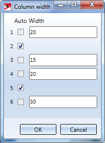
If you activate the Auto checkbox for a column, the width will be automatically determined according to the width of the text. Deactivate the checkbox if you want to enter the column width manually.
Decimal places / Display non-relevant decimal places
For each numerical text block you can set the number of decimal places of attribute values in annotations. You can also specify that even non-relevant decimal places (e.g. final zeroes) are to be displayed by activating the same-named checkbox.
If Standard has been selected for Decimal places (i.e. no decimal places have been specified in the FTD file), the setting from the file Pos3DParNeu.dat will be used for the number of decimal places (Default setting: 0).
Reference line
If the Reference line checkbox in the Total area has been activated, the annotation will be created with a reference line (aka leader line). In this case you can define the representation of the reference line in the Lines area.
You can specify the
- Line colour,
- Line type,
- Base point (i.e. the symbol at the start of the reference line), and
- Size (of symbol).
In the Size field you can freely set the length of the symbol. The Angle is set to 15° according to standard. If you choose Standard as Size, the value set at Arrow length/angle (4.0 15°) or Arrow length/wdith (4.0 1.2)in the system file POS3DPARNEU.DAT will be used.
If you want to change the pre-setting in the system file POS3DPARNEU.DAT, you need to modify the line beneath
Arrow length/angle (4.0 15°) or Arrow length/wdith (4.0 1.2)
accordingly. You have the following options:
- Length and angle (Specification with degree symbol °) of the arrow, e.g. 4.0 15°
or
- Length and width of the angle, e.g. 4.0 2.3
If you use template files (FTD files), the symbol length will be entered when saving the file. If old FTD files are used, the default arrow length from the file POS3DPARNEU.DAT will apply.
Load and Save Settings
You can save annotation settings as a file. The file format is .FTD. The HiCAD SYS directory contains various FTD files with predefined annotations.

|
|
Saves the current settings. The file name extension is .FTD. |
|
|
You use this function to load annotation settings that have been saved to FTD files. The settings defined in the file are displayed in the preview window once they have been loaded. |


Part Annotation (3-D) • Multiple Selection of Texts • Attributes in Annotation Tags