Move Cross-Section
3-D FFS > From c-edge > Move cross-section 
This function enables you to create freeform surfaces
- by connecting at least two cross-sections (which need not necessarily be planar) or
- by placing cross-sections on one or several guidelines (which may also be curved).
The cross-sections as well as the guideline curves must belong to a Sketch.
 If there are several cross-sections, all cross-sections must have the same number of edges!
Proceed as follows:
- If you want to place the cross-sections on guidelines, activate the appropriate checkbox (otherwise continue with 4.).
- Click Select guidelines
 and identify the guidelines in the drawing. All selected guidelines are displayed in the list box of the dialogue window. If you want to remove guidelines from the list, click
Remove guideline ...
  and identify the required guideline in the drawing.
- If you want to specify a direction vector, activate the appropriate checkbox (otherwise continue with 4.) Click the Direction vector
 icon and specify the direction by identification of an edge or specification of 2 points. If several guidelines have been selected, this option will not be available!
 - Choose Select cross-section
 and identify the cross-section in the drawing. All selected cross-sections will be shown in the list box of the dialogue window. If you want to remove cross-sections from the list, click Deselect cross-sections
  and identify the cross-section in the drawing.
 - If you want to reference the part directly after creation, activate the Referenced checkbox.
- Specify the part name of the new freeform surface.
- To display a preview of the part, activate the Preview-button. You can then correct the entered values or insert the part into the drawing by clicking the Apply button. After clicking the Create button, the part will be inserted into the drawing immediately.
The options Preview, Cancel, Create and Apply can also be selected via a context menu. Activate this menu by a right-click outside the input window. If a preview is already shown, it will only be updated after changing the values in the input fields if you confirm the value input with ENTER.

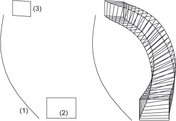
(1) guideline curve, (2) and (3) cross-section

(1) guideline curve, (2) and (3) cross-section
![]() To receive the best possible sweep surfaces, you should keep the following in mind:
To receive the best possible sweep surfaces, you should keep the following in mind:
- How many guidelines are required?
- Generally, you should always create parts with a minimum of guidelines.
- One guideline will be sufficient if the cross-section from which the part is created is to remain equal for the entire part.
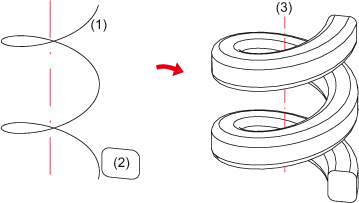
- If one guideline would normally suffice, but the part "slips" during the sweep process, you can restore the perpendicular position by direction specification. This applies in particular to sweeps along helical guidelines.
- Two guidelines are used ift the type of the cross-section is to remain equal, i.e. if you want, for instance, the trimmings in a sweep part to remain circular, but with different radiuses. Furthermore, using two guidelines prevents the slipping of complex cross-sections. It also helps the user make rough outlines of the borders of a part.
- Three guidelines are used if you want to additionally compress or warp a cross-section during sweeping, for instance if you want to gradually convert a circular cross-section into an oval one. A swapping of the guidelines does not necessarily produce the same result. The priority of the guidelines is determined by their selection order. The first guideline is the most important one, while the third guideline is the one with the least influence on the part form.
- Avoid self-intersections
- Generally, self-intersections occur if the radius of the guidelines is too small in comparison with the radius or the width of a cross-section.
- A sweep is better protected against self-intersections if the cross-section is placed at the outer side of the curved guidelines.
- The parts should be roughly pre-defined by guideline and cross-section(s).
- Generally, the desired sweep part is more likely to fulfil the requirements if the cross-section is placed in the immediate neighbourhood of the guidelines.
- Cross-sections which are rather remote from the guideline tend to produce results which are, at first glance, rather implausible to the user.
- The guideline must not contain any sharp bends (Angle >0°).

Surface from C-Edge (3-D FFS) • Overview of Functions (3-D FFS) • Freeform Surfaces
