Surface from Polyline Frame
3-D FFS > From c-edges > Surface from 3-D polyline frame 
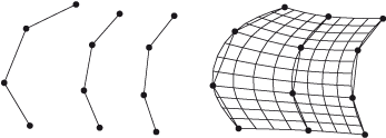
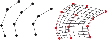
Use the functions of this menu to derive freeform surfaces for a frame. A "frame" is a set of composite edges with an equal number of individual edges and an equal orientation. The c-edges must belong to the same c-edge part. In most cases you would use the Cross-section, Place function to create a frame.
The resulting freeform surfaces can then be modelled and manipulated with the functions of the Process function group on the 3-D FFS tab. In order to change the surface representation, e.g. via changing the number of parameter lines in n- and m-direction, use the functions of the Settings menu.
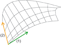
Parameter lines in n- (1) and m-direction (2)
 Please generally note the following when creating a freeform surface from a frame:
- If the active part is a 3-D dummy part or a part with free surfaces, the freeform surface is assigned automatically to this part. Otherwise, HiCAD will create a new part.
- If the c-edges of the part are closed, you can determine the treatment of the base and top surface. If they are both closed, you will get a solid, which can then be processed further (cuts, bores etc.).
Proceed as follows:
-
Activate the part with frame and call the function.
-
In the Frame field, the name of the active part is displayed. In the Name field, specify the part name of the freeform surface.
-
Then select the creation method for the surface: either Via points or As control points by activating the required option field and selecting the desired entry from the relevant list box.
-
If the composite edges of the frame are closed, you can determine the treatment of the base and top surface of the part via the Surface set/Solids field. If base and top surfaces are closed you get a solid, which can then be processed further (cuts, bores etc.).
-
Click Preview if you want to check the freeform surface before applying it to your drawing.
-
Select OK to apply the freeform surface.

Via points
The parameter lines of the created freeform surface are splines.
|
Cubic |
The parameter lines of the created freeform surface are cubic splines, i.e. they can be continuously differentiated twice, they are smooth, without tangential constraints and interpolating. |
|
Cubic, tangential |
The parameter lines of the created freeform surface are cubic splines, however with tangential constraints. The tangents are detected by the direction of the second point towards the penultimate point of a composite edge. The frame must consist of at least 6 composite edges. |
|
Cubic, Bessel |
The splines from which the freeform surface is derived are determined with the Bessel procedure. The edge tangents are estimated as tangents of a parable interpolating 3 points. |
|
Akima |
The parameter lines of the freeform surface are Akima splines. These are, in contrast to cubic splines, local. Polynomes of the third degree are uses here, too, which can however only be continuously differentiated once within the entire domain of definition. This means that the new composite edge is only determined by the control points in the immediate neighbourhood. As the Akima spline can divided straight lines and planes exactly, it has a less wavy run than the cubic spline. |
As control points
Here you create a B-spline surface via a sequence, respectively mesh, of de Boor points, which are also referred to as control points. B-splines are local, which means that modifications take only effect within a particular parameter range. B-splines become a NURB-surfaces, if you place weights with a value not equal to 0 on their control points. Select the B-spline degree. If the degree is too high, HiCAD will issue an appropriate message.
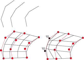
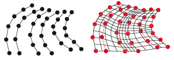
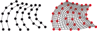
Top: "Frame"; bottom, left: B-Spline; bottom, right: NURB

Interpolate Cross-Sections (3-D FFS) • Overview of Functions (3-D-FFS) • Freeform Surfaces