Linear Dimensioning, Parallel
3-D Dimensioning + Text > Parallel
Use the functions in the functions groups Individual dimensions and Parallel to create individual linear dimensions (structure dimensions) and sets of linear dimensions the dimension lines of which run parallel to one of the axes of the coordinate system, or to a freely selectable reference axis.
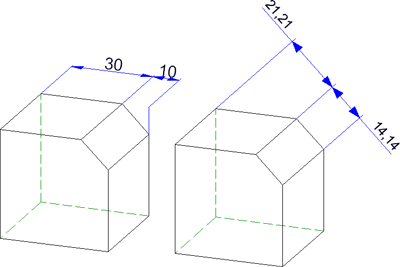
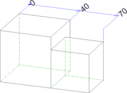
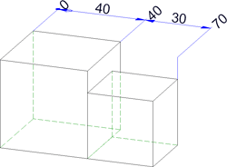
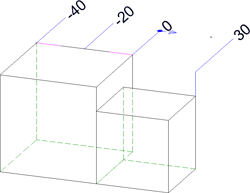
Example: Chain dimension, axially parallel (left) and parallel dimension with chamfer as reference axis
The topics:
- Functions for parallel linear dimensions
- Axially parallel linear dimensions
- Linear dimensions parallel to a reference axis

Functions for parallel linear dimensions
The following functions are available:
| 3-D Dimensioning + Text > Parallel | |
|
|
Create new chain dimension Creates a structure dimension in which two consecutive sub-dimensions have a common dimension point. The dimensions are axially parallel. |
|
|
Create new chain dimension, with reference axis Creates a chain dimension with dimension lines parallel to a selected axis. |
|
|
Create new parallel dimension
Creates structure dimension with all sub-dimensions referring to the same start point and the dimension lines of the sub-dimensions having a fixed distance to each other. The dimensions are axially parallel. |
|
|
Create new parallel dimension, with reference axis Here the dimension runs parallel to a freely definable axis. |
|
|
Create new running dimension Creates a chain dimension with all sub-dimensions referring to the same start point (the reference point). The dimension figures will be automatically placed in vertical direction to the dimension line at the end of each sub-dimension. The reference point is indicated by the dimension figure "0". The dimensions are axially parallel. |
|
|
Create new running chain dimension Creates a combination of reference dimension and chain dimension. The dimensions are axially parallel. |

|
Create new running dimension, with reference axis Creates a running dimension the dimension lines of which are parallel to a reference axis. |

|
Create new running chain dimension, with reference axis
Creates a combination of reference dimension and chain dimension. The dimensions are axially parallel to a reference axis. |
|
|
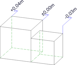
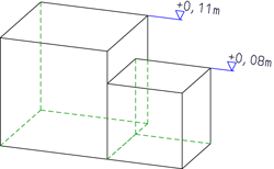
Create new height above datum Special axially parallel running dimension used in Civil Engineering and Steel Engineering. |
|
|
Create new height above datum, parallel to z-axis Height above datum, referring to the XY-plane of the coordinate system Please note:
|
|
|
Create new coordinate dimension Special axially parallel reference dimension, in which the first identified point will be interpreted as reference point. From this point, the absolute dimensions between the reference point and the other dimension points will be detected. The reference point will be indicated by the dimension figure "0". |
|
|
Create new height above datum, with reference axis Special running dimension used in Civil Engineering and Steel Engineering, with dimension lines running parallel to a defined axis. |
|
|
Create new coordinate dimension, with reference axis Coordinate dimension, with dimension lines running parallel to a defined reference axis. |


 >....
>.... 


 Please note:
- The current dimension parameter settings will be considered for new dimensions. Please note that (depending on the settings on the System tab) the dimensions will be projected onto the active processing plane.
- Please also read the information given in the topics Dimensioning - Procedure and Dimensioning - Element Type Selection.
Axially parallel linear dimensions
- Activate the part to which you want the dimensioning to be assigned.
- Choose the desired dimensioning function.
- Determine the base points by selecting any points, edges or surfaces - depending on the settings in the Element type selection dialogue window (see also Dimensioning - Procedure).
- Determine the position of the dimension by dropping it. Use the right mouse button to activate the Dimensioning, Move context menu. This context menu enables you to determine the position of dimension line and dimension figure.
- Determine the next base points in the structure dimension or end the function by pressing the middle mouse button.
Please note:
- Individual axially parallel linear dimensions can also be determined with the Variable dimensions
 function or the
  Linear dimension, axially parallel function iin the Individual dimensions menu.
 - Use the Half-section-dimension, axially parallel
 function in the Individual dimensions menu for creating axially parallel half-section dimensions.
 - For half-section dimensions you need to specify the symmetry axis before selecting the elements to be dimensioned!
Linear dimensions parallel to a reference axis
- Activate the part to which you want the dimensioning to be assigned.
- Choose the desired dimensioning function.
- Determine the reference axis.
- Determine the base points by selecting any points, edges or surfaces - depending on the settings in the Element type selection dialogue window (see also Dimensioning - Procedure).
- Determine the position of the dimensioning by dropping it. Use the right mouse button to activate the Dimensioning, Move context menu. This context menu enables you to determine the position of dimension line and dimension figure.
- Determine the next base points in the structure dimension or end the function by pressing the middle mouse button.
Please note:
For the creation of individual, linear dimensions running parallel to a reference axis you can also use the Variable dimensions function or the Create new linear dimension, with reference axis  function in the Individual dimensions menu.

Dimensioning (3-D) • Dimensioning - Procedure (3-D) • Linear dimension, free (3-D) • Dimension parameters (3-D)