3-D Dimensioning + Text > Parallel > Variable dimensions
This function is a smart, variable dimensioning function that combines a multitude of individual dimensioning functions:
It is thus possible to quickly create
- axially parallel or free linear dimensions,
- angular dimensions between two edges or surfaces,
- angular dimensions between an edge and the X-, Y- or Z-axis,
- arc dimensions,
- circle, radius and diameter dimensions, and
- Linear structure dimensions.
with only one function. Depending on the selected element, e.g. edge, full circle or point, it directly creates the "correct" dimension or, if several dimensions are possible, allows you to choose the desired dimension.
Proceed as follows:
- Activate the part that you want to dimension.
- Choose the Variable dimensions function. The dialogue window show below will be displayed:
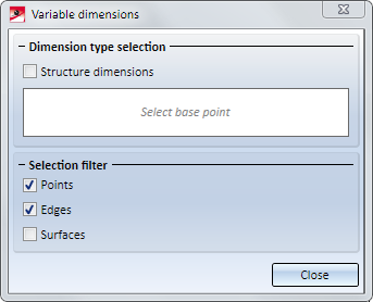
If you want Structure dimensions to be detected as well, activate the same-named checkbox.
- HiCAD will then prompt you to specify the base point. You can do this by selecting a point, an edge or a surface. In the Selection filter section specify which elements - points, edges or surfaces - you want to allow for selection by activating/deactivating the checkboxes.
- Now, select the desired element with the cursor.
- If dimension types can be detected automatically they will be listed beneath Dimension type selection. The last selected dimension will be highlighted there and will be shown as a preview in the drawing. The dimension is attached to the cursor and can be directly placed at the desired position.
- If no dimension can be detected via the base point selection HiCAD will request you to select more base points until a dimension type can be detected. If you have for example selected a point, then it requires another point or edge to be selected before a dimension type can be determined.
- If a dimension is attached to the cursor, the prompt Select further base point or drop dimension is displayed in the info bar at the bottom left of the HiCAD window.
- Drop dimension
Beneath Dimension type selection, mark the desired dimension type and drop this dimension, i.e. you determine the position of this dimension in the model drawing. Prior to position determination you can right-click and open a context menu with further functions. For instance, you can choose a different dimensioning plane, freely move the dimension figure, etc.
For structure dimensions you can specify several consecutive points after dropping the first dimension. The selection of the consecutive points can be ended by pressing the middle mouse button. After this, the base point selection will be active again.
Important:
For structure dimensions you first need to specify all consecutive points before dropping the dimension. End the selection of the points by pressing the MMB. Then, the base point selection will be active again.
- Select further base point
Determine further base points. For example, if you have selected 2 points, the dimension types Linear dimension, axially parallel , Linear dimension, free and Linear dimension with reference axis will be detected and the linear dimension will be attached to the cursor. When you specify another base point , the dimension type will be switched to Angular dimension.
If no further base point selection is possible, you will be asked to drop the dimension. Press the middle mouse button to end the function.
- If you have dropped a dimension the Dimension type selection list will be deleted and you can create further dimensions. Via Cancel you exit the function. Dimensions that have not been dropped yet will be lost.
 If you choose the dimension type Linear dimension with reference axis or Angular dimension with reference axis you need to determine a reference axis. In this case HiCAD will prompt you in the info bar at the bottom of the HiCAD screen to select a reference axis - either by identifying an edge or by specifying two points. The dimension will then be attached to the cursor.
The selected reference axis will remain active until you select a different reference axis or end the function, i.e. if you select the dimension type Linear / Angular dimension with reference axis in the dialogue window again, the previously selected reference axis will be used. If you want to select a different axis, click on the button and define the new axis.
The following table provides an overview over the possible dimensions for the different base points.
|
Base point |
Dimension |
Selection |
|---|---|---|
|
2 points |
Distance of points |
|
|
Edge |
Length of edge |
|
|
Edge + point |
Distance between edge and point |
|
|
2 parallel edges |
Distance between edges |
|
|
2 intersecting edges |
Angle between edges |
|
|
3 points |
Angle between points |
|
|
Full circle |
Diameter or radius |
|
|
Full circle + edge |
Distance between circle and edge |
|
|
Circular arc |
Radius, diameter or arc |
|
|
Surface of a sphere, a cylinder, a cone or of a torus |
Diameter or radius |
|
|
Surface |
Angular dimension |
|
|
2 surfaces |
Distance of the surfaces or angle between the surfaces |
|
|
Edge + Surface Point + Surface |
Distance between edge and surface Distance between point and surface |
|
* only if the Structure dimensions checkbox is active
Which of the dimensions will be preset depends on the cursor position during the selection of points, edges or surfaces.
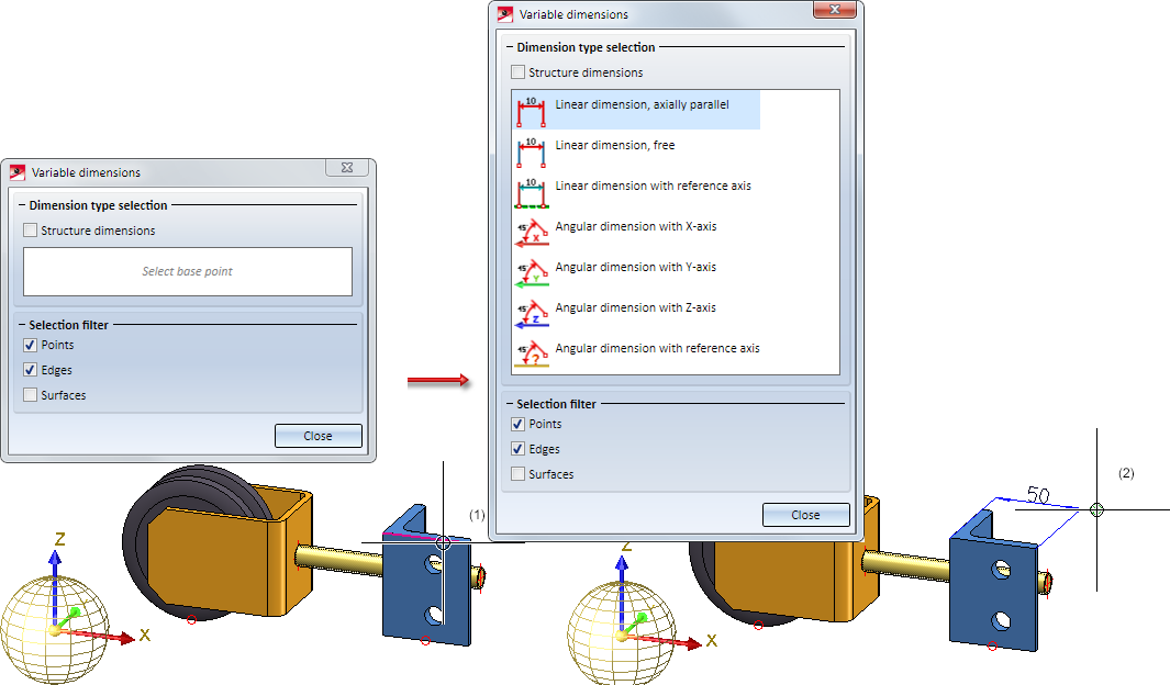
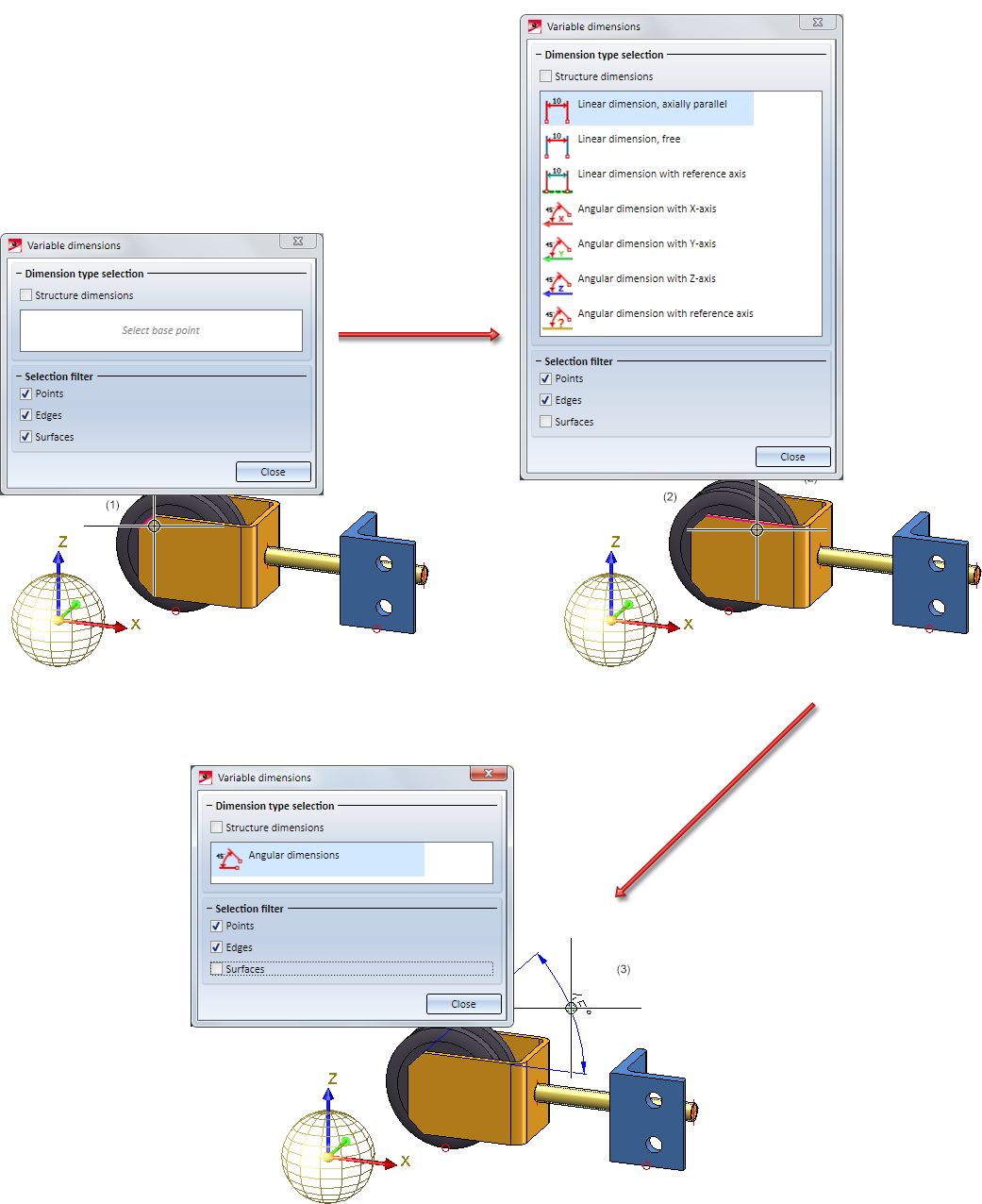
Example 1: Edge selected
In the image below, the highlighted edge (1) has been selected after calling the function. In this case, the function will suggest the linear and angular dimensioning types (2).
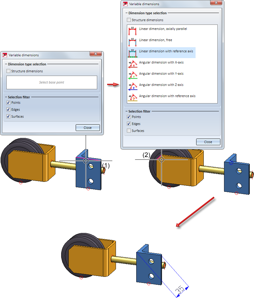
In the following image a reference axis is to be used. First, select, as in the other example above, the edge (1) and then select the dimension type Linear dimension with reference axis. Next, select the edge (2) as reference axis.
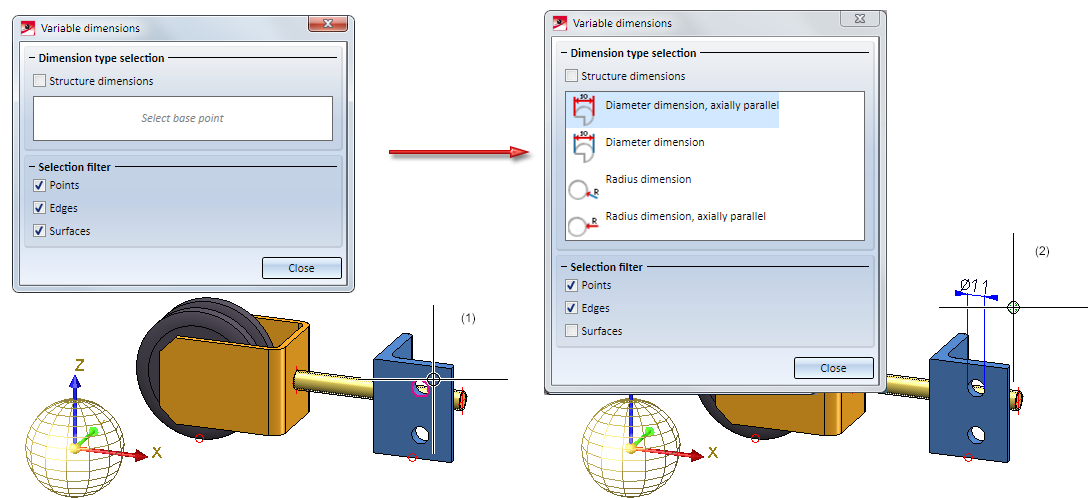
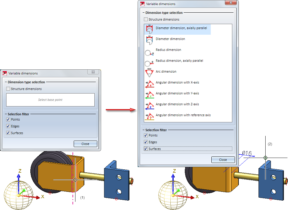
Example 2: Circle selected
Here, one of the bores (1) has been selected. In this case, the function will suggest the dimensioning types
- Radius dimension, axially parallel (attached to cursor),
- Diameter dimension,
- Radius dimension, and
- Radius dimension, axially parallel.
Example 3: Two edges selected
Here, the edge (1) has been selected first. The function will then suggest the linear and angular dimensions shown below. If you now select another edge (2), the dimensioning type Angular dimension (3) will be suggested.
Example 4: Surface selected
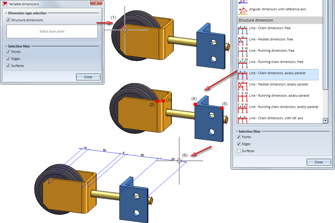
Example 5: Structure dimensions
In this example we want to create a chain dimension with the Variable dimensioning function: First, activate the Structure dimensions checkbox in the dialogue window. Then, select the edge (1). Choose Line - Chain dimension, axially parallel. Next, choose the consecutive points (2) - (5), and drop the dimension (6).
![]() Please note:
Please note:
- Please also read the information given in the Dimensioning topic.
- If you want to install a bore with thread as a standard part and conduct a diameter dimension the dimension will be processed as a thread dimension. Instead of the diameter sign an M (metrical thread) will be placed in front of the dimension figure. If the diameter sign should be used instead of the thread sign this setting can be changed in the Configuration Editor: Go to ... > Drawing > Annotations > Dimensioning, 3-D > Interactive dimensions, deactivate the Thread designation checkbox in the Dimension figure section.
- Circle, radius and diameter dimension can be rotated around the centre with the mouse. Moreover, the dimension figure can be moved. The positioning of the dimension only happens when the mouse button is released. The same applies to parametric dimensions.
The angle grid for the rotation can be adjusted via the dimension parameters and refers to the dimensioning coordinate system of the original dimension. Alternatively, the grid can be adjusted in the Configuration Editor. To do so change the Angle grid in the section Grid via ... > Drawing > Annotations > Dimensioning, 3-D > Interactive dimensions(default 7.5).


General Notes on Dimensioning (3-D) • Dimensioning - Procedure (3-D)