Dimensioning - Procedure
- Activate the part you want to dimension.
- Select the desired dimensioning function.In all dimensioning functions, you can then activate the Element type selection dialogue window with a right-click (for the Variable dimensioning you can make the selection directly in the dialogue window).
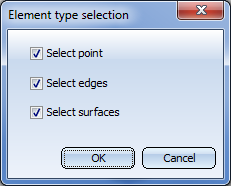
With the available options you specify which elements (points, edges, or surfaces) you want to allow for base point determination. The dialogue window can be activated each time HiCAD requests the identification of an element to be dimensioned.
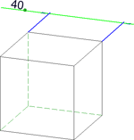
- Determine the requested base points. Depending on the chosen element types, these can be points, edges or surface. HiCAD will mark the identified elements with a small symbol:
 for points,
  for edges,
  for surfaces.
 - After selecting all elements and determining the dimensioning base points, HiCAD will display the dimension next to the cursor. The plane to which the 3-D dimension will be applied depends on the active coordinate system and the view, respectively circular plane.
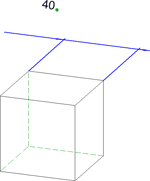
- You can now place the dimension line dynamically with the cursor (i.e. drop the dimension line). Apply the new position by a left-click.
Before applying the position, you can activate the Dimensioning, Move menu with a right-click. In this menu, the following options are available to the user:
|
|
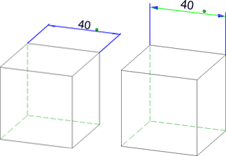
Dimension figure + Dimension line Free positioning of dimension figure and dimension line with the cursor. |
|
|
Dimension line Free positioning of the dimension line (default) |
|
|
Dimension figure, parallel Move the dimension figure parallel to the dimension line |
|
|
Dimension figure, free Move the dimension figure freely. |
|
|
Switch to Z-X plane Switch to the Z-X plane of the active dimensioning coordinate system. |
|
|
Continue Back to the dimensioning function |


 Please note:
- If you want to align the dimension line exactly to an already existing dimension, move the cursor to the existing dimension line. The line will be highlighted in a colour and identified with the symbol
 . Next, press the left mouse button.
 - 3-D dimensions are placed with the help of a grid, which can be defined via the Dimensioning settings.
- You can also use Drag & Drop to subsequently move dimension lines and dimension figures. Press and hold down the left mouse button. Place the dimension at the required position and drop it with a left-click.
- Before dropping the dimension at the new position, you can activate - as you would do when creating new dimensionings - the Dimensioning, Move menu with a right-click.
- When creating dimensionings, processing planes may also be taken into account. For this purpose you need to set the Dimensioning parameters accordingly.
- If you close the Element type selection dialogue with Cancel, the function will be ended without creating the dimensioning.


Dimensioning (3-D) • General Notes on Dimensioning (3-D) • Dimensioning - Element Type Selection