Surface Finish
3-D Dimensioning + Text > Surface/Edge > Surf...
Use this function to assign a surface symbol to a part. The Surface specifications window is displayed.
Proceed as follows:
- Define the desired surface specifications in the dialogue window.
- Click OK to close the window. The character is now placed in the drawing.
- Identify an edge or a cylinder of the part to which you want the character to be assigned.
- Specify the reference point (insertion point) of the surface character.
- If you want to create the character with leader line, you have now the option to draw the leader line by specifying a start point, intermediate (fold) points and an end point. You end the leader line creation with a right-click.
If you do not want a leader line, right-click immediately after specifying the reference point.
The character is now aligned as follows:
- without leader line
on the selected edge - with leader line
on the last segment of the leader line
With and without leader line: (1) Edge, (2) Reference point
The SURFSYM.INI file
In connection with the surface characters the system file surfsym.ini in the HiCAD SYS directory plays an important role.
This file has the following purposes:
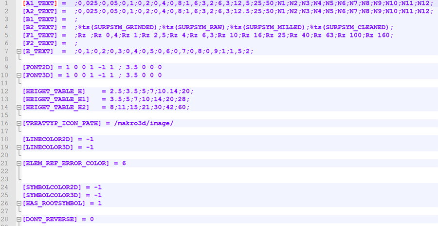
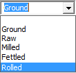
- In this file you can determine the contents of the selection boxes of the Surface specification dialogue window. This is done in the lines 1 to 7, i.e. from A1._TEXT to E_TEXT.
For instance, if you expand the line B2_TEXT by "Rolled", this new entry can then be chosen from the selection box.
[B2_TEXT] = ;%ts(SURFSYM_GRINDED);%ts(SURFSYM_RAW);%ts(SURFSYM_MILLED);%ts(SURFSYM_CLEANED);Rolled
HiCAD uses the keyword %ts to gain access to the internal text service. This will not be required for your own additions, though.
- Here, the default settings of surface characters for new model drawings are defined. The default settings can be changed at any time via 3-D Dimensioning + Text > Surface/Edge > Surf...
 > Settings
 .
.


Dimensioning (3-D) • Texts and Annotations (3-D) • Define Surface Information • Modify Surface Symbols