Project: HiCAD Dach/Wand/Fassade
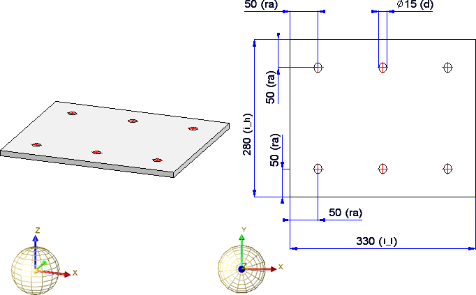
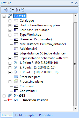
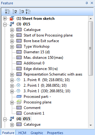
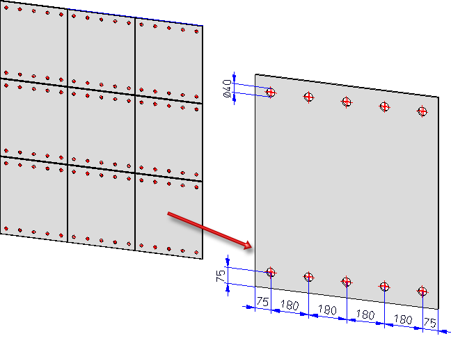
In the following example we will use a drilled Steel Engineering plate as installation element. The plate is to be derived from a sketch. Width and length are to be variable. The bores are to be arranged linear and equidistant (even) manner onto an axis. The number of bores is to be determined automatically on the basis of the maximum grid distance. The diameter of the bores, the distance of the bores to the plate edge and the maximum grid distance is to be variable.

The first step towards your own installation element is the definition of the part's geometry. Construct the part with the corresponding HiCAD functions.
 Make sure that the Feature log is activated!
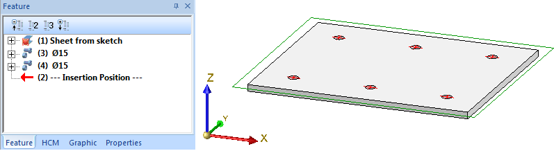
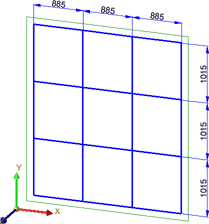
Example:
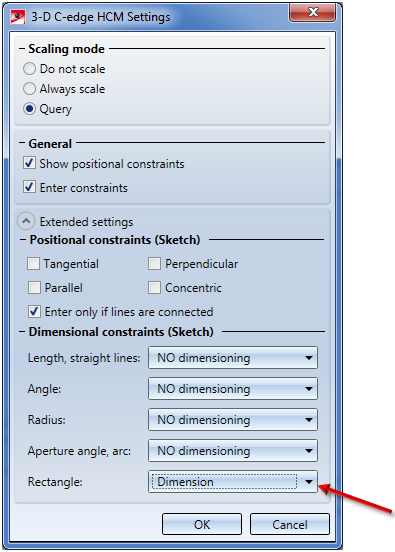
 to create a new sketch.
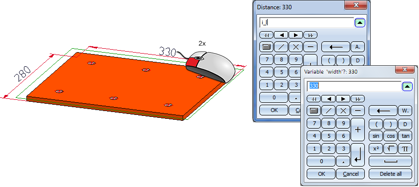
  . In the Extended settings, select the Rectangle: Dimension setting (these parametric dimensions are to be used later on).
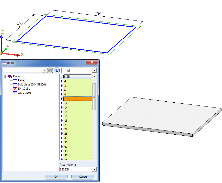
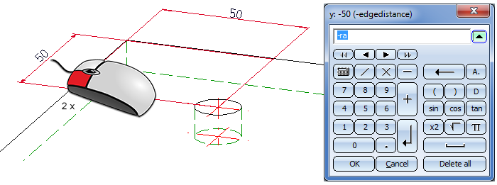
 and draw a rectangle with the dimensions 330 x 280.
  to derive a Steel Engineering plate from the sketch.
 .
.
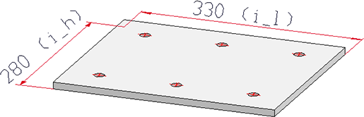
To ensure that the installation element will be automatically adjusted to the utilized sketch it needs to be parameterized. This is done by assigning variables or formulas and - if required - by assigning of HCM constraints.
In any case, the variables
for the width and the height of the installation element must be used!
You can assign these variables either
Some functions also allow a direct use of variables.
Please note that the parametric dimensions will only be displayed if the visibility settings for this type of dimensioning have been set accordingly. These can be specified via the Properties Parametric dimensions function in the context menu for parts. In this example you should select the If feature active option.
Important:
If the installation element is an assembly, all utilized variables must be assigned to this assembly!
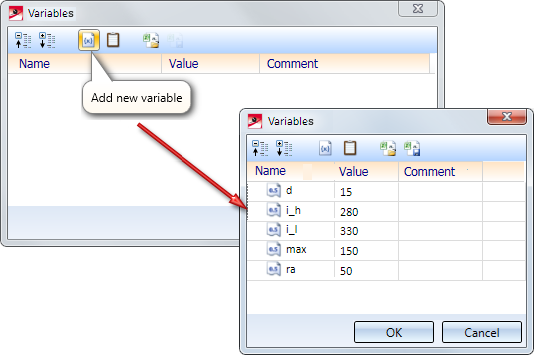
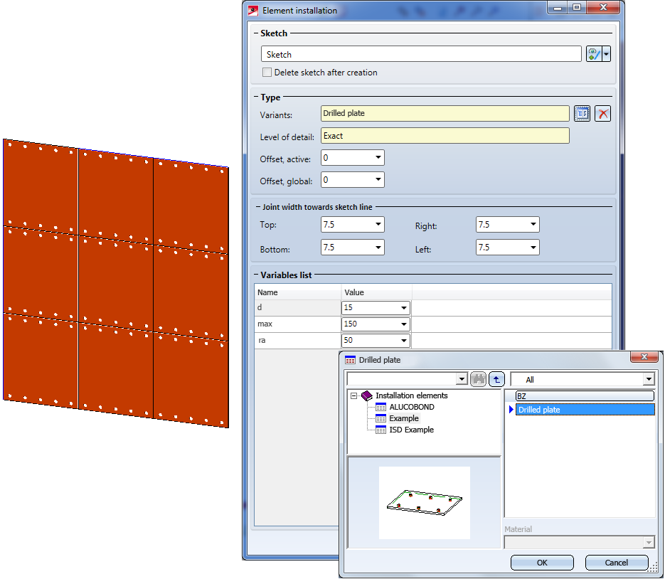
Let us assume that the plate in this example belongs to an assembly, and this assembly is to be used as an installation element. In this case the parameters i_l, i_h, d, max and ra must be assigned to the assembly. To do this, right-click the name of the assembly in the ICN and choose Properties > Part variables. Then, select Add new variable in the Variables dialogue window and enter the name of the variable and its start value.
The plate can then be parameterized as described above.
The Fitting CS (FCS) determines the insertion direction of a part in space. It consists of 3 special points:
If a 3-D part to which an Fitting CS has been assigned is loaded into a new model drawing, the points of the Fitting CS will be placed into the World CS. This defines the fitting direction in space.
The definition of a Fitting CS is particularly important if the installation element is an assembly. If this assembly is saved to the Element installation catalogue and no Fitting CS has been assigned to it, a Part CS of the assembly will be used as fitting coordinate system during its insertion. Please note that this can led to unwanted effects during the installation of the elements.
 Please note:
Not all assemblies have automatically a Feature log, e.g. assemblies that have been created with the Form assembly function, or, in case of the creation of new assemblies, with the New assembly function. If you assign a Fitting CS to these assemblies, no corresponding Feature entry will be created. To achieve its creation, you need to assign a so-called body creation feature to the assembly. To do this, right-click on the Feature window of the assembly and choose the corresponding function in the context menu. After this, the definition of the Fitting CS will be entered as a Feature for these assembly types, too.
Continuation of the example:
As already mentioned, the sheet in this example is to be inserted in such a way that the bottom left corner lies in the bottom left corner of the selected sketch area. Therefore, a Fitting CS must be defined for the Sheet Metal main part
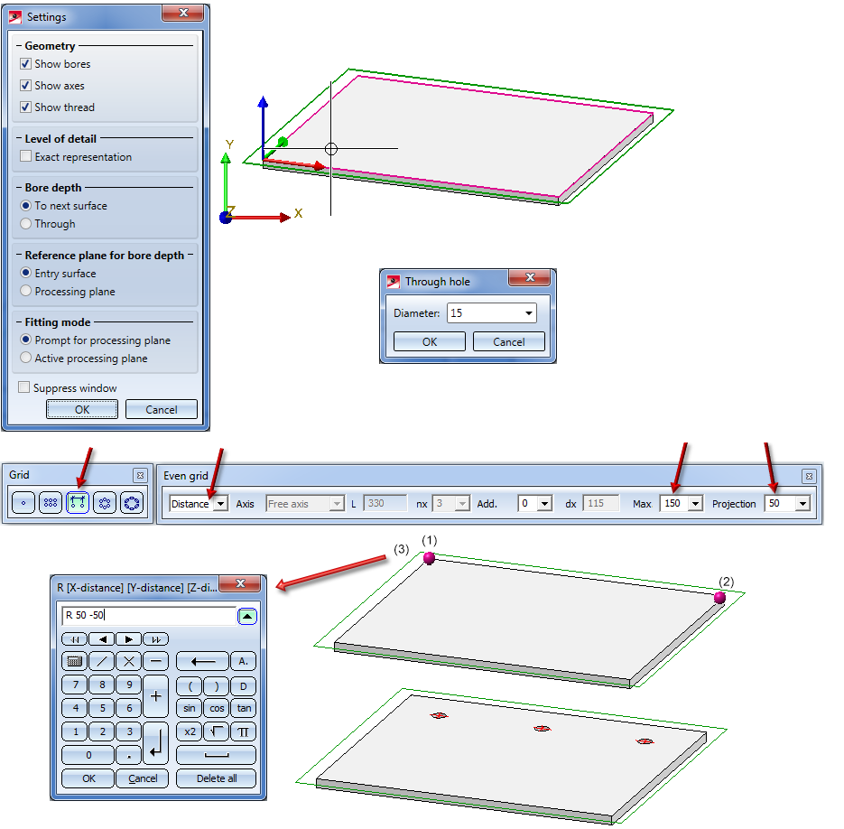
On the Drawing tab, choose Others > World CS  > Define Fitting CS
  . Define the points as follows:
(1) New origin of the coordinate system
(2) Point on the X-axis
(3) Point on the Y-axis
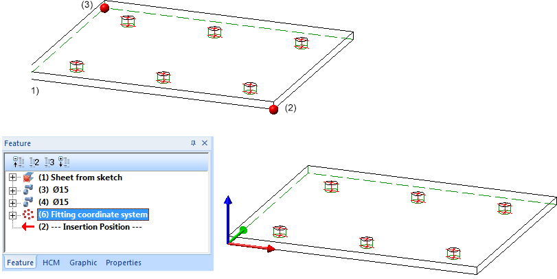
The Fitting CS will then be entered in the Feature log.
The installation element is now completed and can be saved to the catalogue.
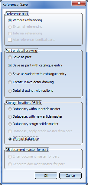
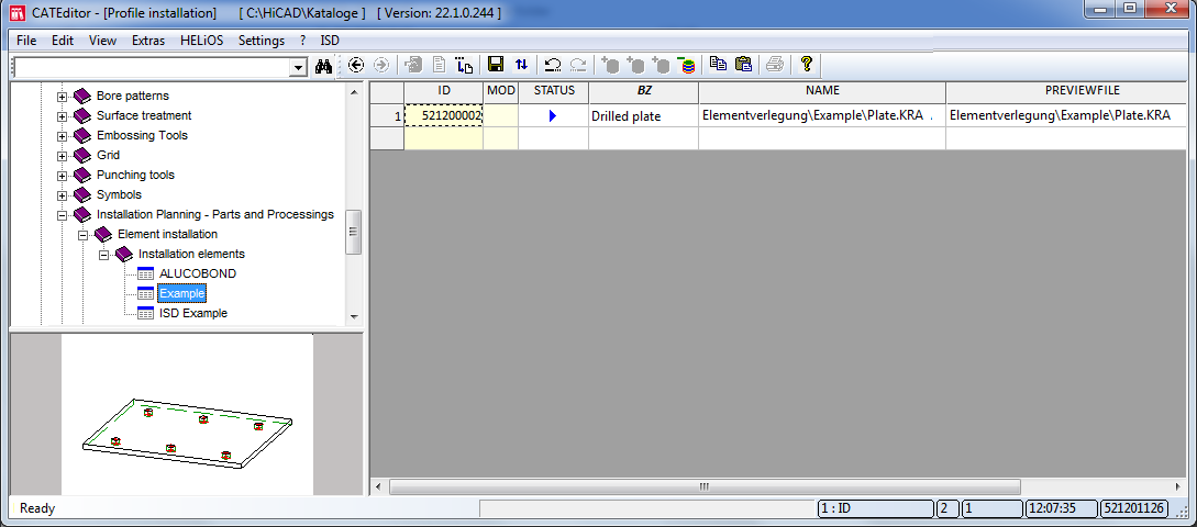
To save an installation element to the catalogue, activate the Drawing tab and select Save/Reference > Part..  . use the settings as shown below. In our example, make sure that the main part of the plate is active.
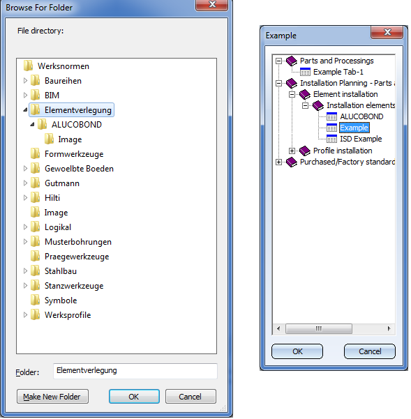
In this example the Element installation folder and the Example table have been selected. The required structure of tables for element installation is explained in the topic The "Element Installation" Catalogue.
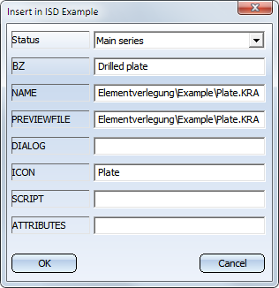
with Yes. A preview image of the data record Drilled plate will then be created, namely, in the folder Kataloge\Werksnormen\Elementverlegung\image.
Result

Element Installation • Catalogue Editor
|
© Copyright 1994-2019, ISD Software und Systeme GmbH |