
Project: HiCAD Basics
Drawing > Others > World CS
You can access the functions for 3-D coordinate systems via Drawing > Others > World CS.
|
|
Activates the standard coordinate system. |
|
|
Activates the coordinate system assigned to a 3-D part. |
|
|
Temporarily creates a local coordinate system by defining a 3-D processing plane. |
|
|
Local CS, New origin Moves a coordinate system by defining a new origin. |
|
|
Local CS, Rotate about X-, Y- or Z-axis Rotates a local coordinate system or a part coordinate system about the
|
|
|
This function enables you to define a fitting coordinate system for the active 3-D part in the same way as for creating 3-D processing planes. It has the following special properties. |

|
Delete Fitting CS, Active part Deletes the fitting coordinate system of the active part. |

|
Delete Fitting CS, Active part and sub-parts Deletes the fitting coordinate system of the active part and its sub-parts. |
 In Steel Engineering the orientation of inserted beams is graphically indicated by means of a coordinate system.

Drawing > Others > World CS > World CS
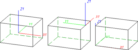
You use this function to switch to the world coordinate system (standard coordinate system). This coordinate system is automatically active when a new drawing is created. Its reference point lies in the point (0,0,0), while the xy-plane is the top view plane. By choosing another view and by moving the screen display, you can change the position and the orientation of the world coordinate system even before you start your drawing.
![]() Please note:
Please note:
Drawing > Others > World CS  > Activate Part CS
You use this function to activate the part coordinate system of the active 3-D part. A part coordinate system is automatically assigned to every 3-D part of your drawing when it is created and saved together with the drawing.
![]() The Part CS cannot be modified!
The Part CS cannot be modified!
Drawing > Others > World CS > Processing plane 
This function enables you to define a local coordinate system temporarily by specifying a processing plane.
To specify the processing plane, you can identify points, edges, surfaces and even processing planes in the drawing. You can access further functions for specifying the processing plane by pressing the mouse button instead of making an identification.
![]() The local coordinate system remains active until you define a new one
or switch intermittently to the world coordinate system or a part coordinate
system.
The local coordinate system remains active until you define a new one
or switch intermittently to the world coordinate system or a part coordinate
system.
Drawing > Others > World CS > Define Fitting CS 
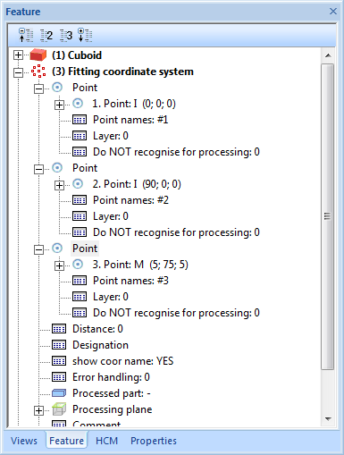
This function enables you to define a fitting coordinate system in the same way as when creating 3-D processing planes. This coordinate system determines the fitting direction when inserting a stored 3-D part in the drawing. The Fitting CS consists of 3 special points, to which point designations from #1 to #3 are assigned:
If a 3-D part to which a Fitting CS has been assigned is loaded into a new drawing, the points of the fitting coordinate system are placed in the world coordinate system. This defines the fitting direction in space. The exact position in space is defined, as usual, through specification of a fitting point pair.
Please also read the notes on the Fitting Coordinate System for Referenced 3-D Parts.
The fitting coordinate system will be entered as a same-named feature step into the Feature log. There you can assign an additional designation to the Fitting CS which will then be shown both in the feature log and in the drawing.
An example:
The following figure shows a sheet. In the first step, this sheet without fitting CS has been saved with the function Drawing > Reference > Part.. , for instance with the name Without_FCS. This part was then built into a new drawing using the Explorer (2). Then a fitting CS was defined for the sheet metal in the original model drawing (3) by determining the points P1, P2 and P3 (left lower / right lower / left upper corner of the red surface). Then the sheet was saved again, for example With_FCS. This sheet metal was then also built into the new construction (4). You can clearly see that the fitting direction has changed. P1', P2' and P3' are the fitting CS points transferred to the World CS.

 Important:
function is then applied to this part, the previously defined fitting coordinate systems will still be shown in the feature log. After a recalculation, the last but one fitting coordinate system will apply.
Drawing > Others > World CS > Delete Fitting CS, Active part
Drawing > Others > World CS > Delete Fitting CS, Active part and sub-parts
Use these functions to delete the fitting coordinate system of the active part and, if desired, also of its sub-parts.

|
© Copyright 1994-2019, ISD Software und Systeme GmbH |


