Project: HiCAD Dach/Wand/Fassade
The following example explains the procedure for the creation of a customer-specific dialogue with the help of the HiCAD GUI Creator.
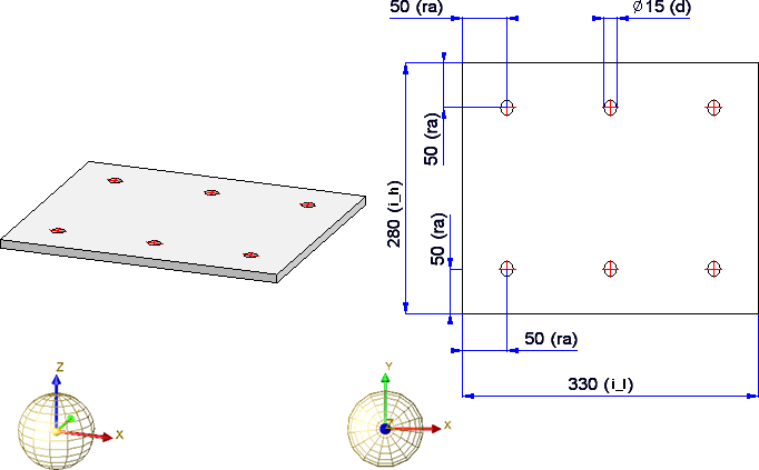
In this example we will use the following drilled plate:
Before creating the dialogue, expand the example as follows:
In this example a particular semi-finished product was formerly used, namely a plate taken from the table Plates (Table ID 127) with a thickness of 10 (Row ID 3). Here, however, we would like to be able to freely choose the semi-finished product when inserting the part. Therefore, we will define an additional variable of the type List. For this to happen, right-click on the plate in the ICN and choose Properties > Part variables. Then, choose Add variable  and insert a variable, e.g. hz of the type List. Next, right-click on the row representing the new variable and choose Add new variable. You do not need to enter the name here, as it will be determined automatically. Select the variable type Number and, as start value, the Table ID, e.g. 127, for the table Semi-finished products > Plates > Plate. After closing the dialogue with OK, the sub-variable will be displayed, with the name being a consecutive number in square brackets, e.g. [1]. Proceed likewise to create the variable for the Row ID.
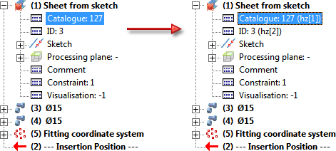
In the Feature of the plate ("Sheet from sketch"), enter the variables hz[1] and hz[2] for Catalogue and ID, respectively:
Now you can start with the design of the user interface.
Start the HiCAD GUI Creator by running the file
HiCADGUICreatorApp.exe
in the HiCAD EXE directory.
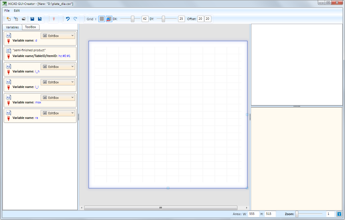
The HiCAD GUI Creator dialogue window will be displayed. Choose New to create a new dialogue. For this you will need the previously saved file plate_dia.csv.
On the Variables tab you will find all variables that were assigned to the plate.
How is the dialogue supposed to look?
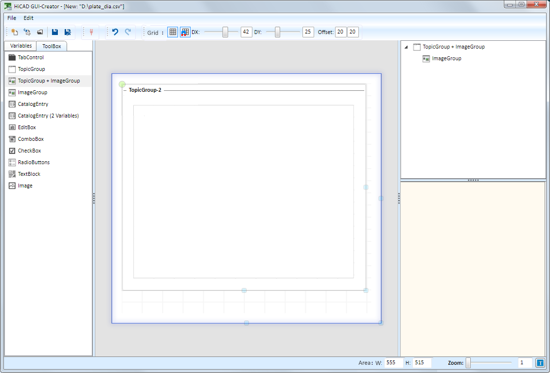
This means that we require a TopicGroup+ImageGroup.
Step 1: Insert the ToolBox object TopicGroup+ImageGroup
To do this, just drag the required object from the ToolBox into the dialogue.
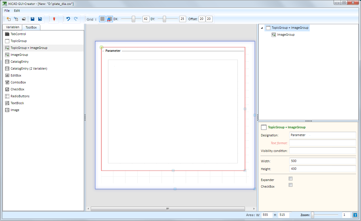
Then, mark the TopicGroup (red frame) and edit the parameters as required, e.g.:
Schritt 2: Fill the ImageGroup with content
As mentioned above, the ImageGroup is to obtain the fields
Mark the ImageGroup and drag the corresponding variables into the object.
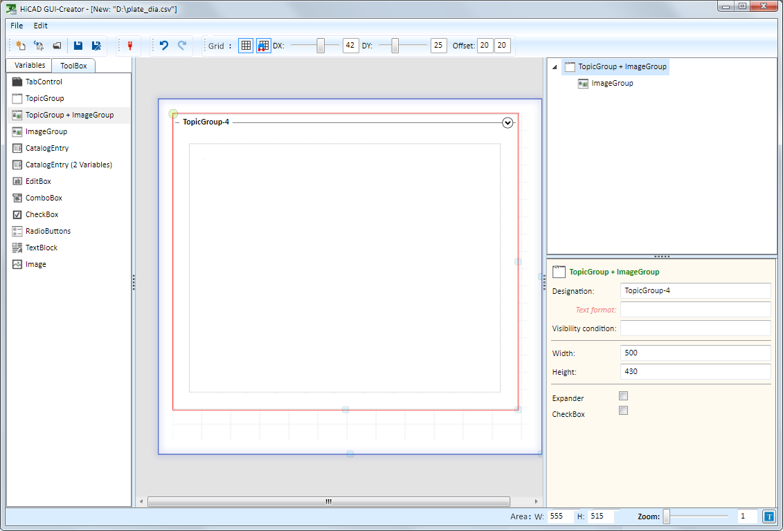
The variables are aligned like tables.
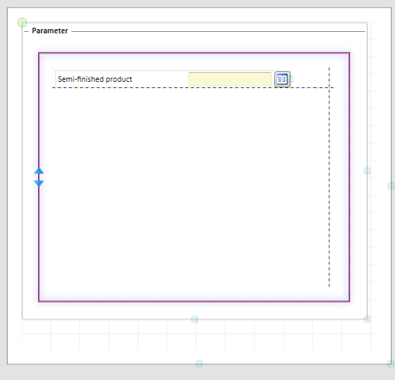
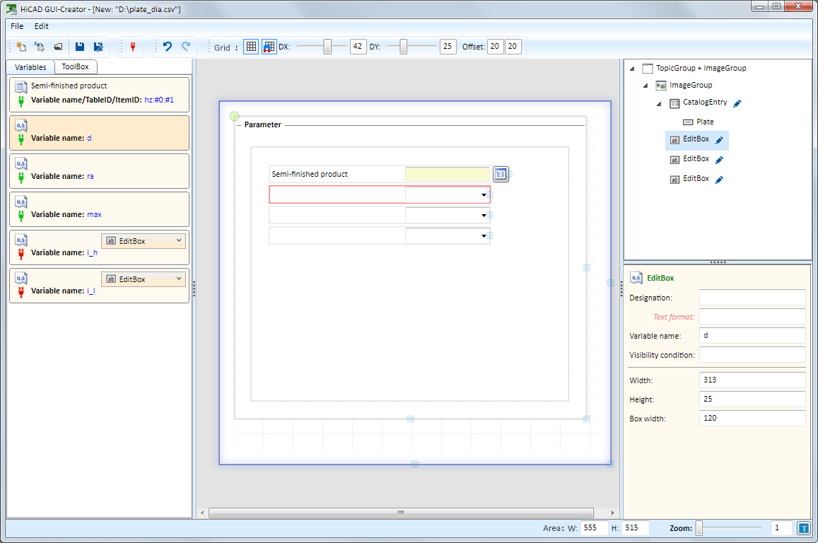
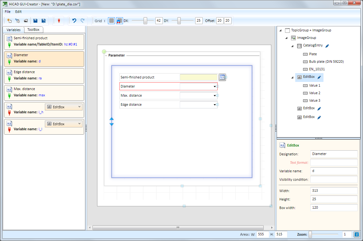
Step 3: Edit the parameters
Now you can edit the parameters of the fields.
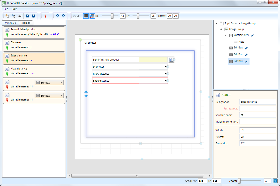
 in the tree structure, you can edit the catalogue selection or the selection box.
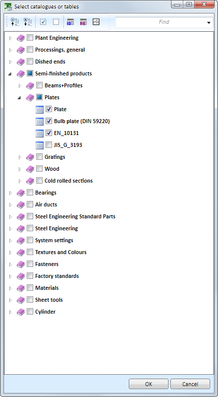
 For instance, you can determine the catalogues for the semi-finished product selection:
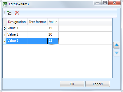
Or you can assign values for the diameter:
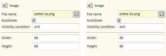
Step 4: Insert the images
Now, insert two images, namely:
 one for Diameter > 0 and
 one for Diameter = 0.
For this two ToolBox objects of the type Image are required, which will be simply dragged from the ToolBox into the ImageGroup.
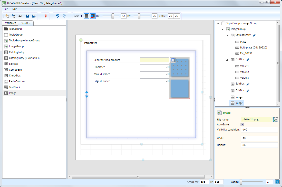
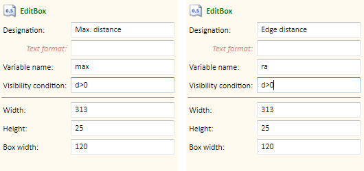
For both images you need to define a Visibility condition.
Step 5: Save the dialogue and adapt the catalogue
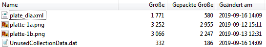
Now you can save the dialogue, e.g. under the name plate_dia.isdgui in the catalogue Element installation > Example.
This file contains the utilized images, the dialogue in the XML format and a list of unused variables.
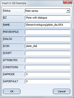
To be able to use the dialogue, it must be assigned to the corresponding installation element, e.g.

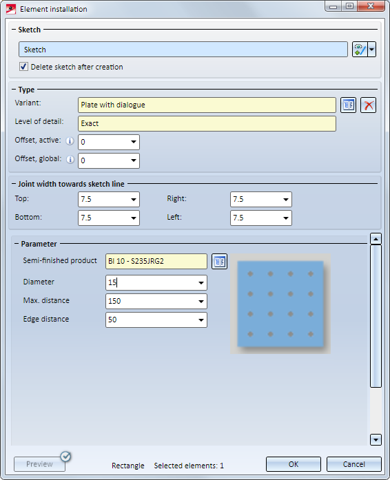
If the installation element is now chosen for the element installation, the following dialogue will be shown:
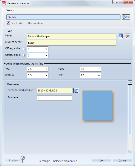
If the value for Diameter is set to 0, the dialogue will look as follows:

The HiCAD GUI Creator • Element Installation • Catalogue Editor
|
© Copyright 1994-2019, ISD Software und Systeme GmbH |