
Project: HiCAD Sheet Metal
Sheet Metal > Further tools > Moulding tools
HiCAD has a library of moulding tools to which you can add your own tools.
This topic is subdivided into the following paragraphs:
(1) Swaging hump
(2) Centring boss
(3) Beading
(4) Through hole thread
(5) Vents
(6) Processing plane
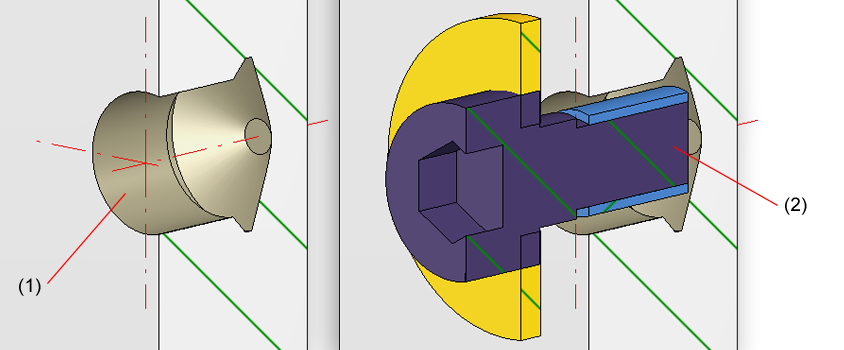
(1) Undercut bore
(2) Undercut bore with bolting

To insert moulding tools, proceed as follows:
The Settings dialogue window will be displayed (if you had not activated the Suppress window option beforehand.
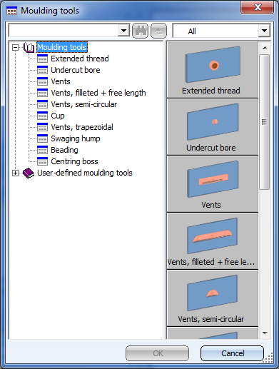
A dialogue window opens, enabling you to choose the required moulding tool.
You can now position one single tool, or, via the displayed Grid menu, arrange a whole group of tools.
You can now insert the tool another time. You can also right-click to open a context menu before determining the new insertion position. You can use the functions of this menu, for instance, to change the insertion direction. Press the middle mouse button to end the function.
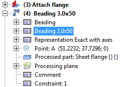
The mould will be entered in the Feature log of the Sheet Metal part and can be changed with a double-click on the entry, e.g. Beading 3.0x50.
You can add your own moulding tools to the library. For this you need at least 2 elements: One sketch used by HiCAD to create a material subtraction in the sheet to be processed, and a part containing the actual processing.
When applying the moulding tool, HiCAD initially uses the sketch to create a subtraction in the sheet; then, the part will be positioned and added to the sheet.
Both parts can be parameterized. The thickness of the sheet to be processed will be used as parameter d; other parameters for the size of the processing can be stored in the catalogue in order to be able to apply a moulding tool with many different sizes (see Example).
When inserting this part its coordinate origin will be used as fitting point. For round processings it makes therefore sense to place the centroid of your model drawing in the origin.
Furthermore, this part must contain three named points: One point with the point number 1 in the origin; one point with the point number 2 which, together with point 1, represents the X-axis; and a point with the point number 3, which defines the alignment to the Y-axis.
Save this part as a *.KRA file t the sub-folder Kataloge\Werksnormen\Formwerkzeuge of your HiCAD installation.
This part contains a (parameterizable) sketch which is inserted at the fitting point and is used for the creation of a subtraction in the sheet. Here, too, the later fitting point should be placed in the origin.
The sketch must contain a named point with the point number ! which defines the fitting point during insertion.
Save this part, too, as a *.KRA file to the sub-folder Kataloge\Werksnormen\Formwerkzeuge of your HiCAD installation.
User-defined moulding tools are stored in the catalogue at Factory standards > User-defined moulding tools. For your own entries you can right-click the table ISD Moulding tool table, duplicate it by choosing New table with template and then adjust this copy according to your requirements.
If you have used further variables for parameterization, you can add these as further columns to this table.
The columns in the table have the following meaning:
A complete example of how to create a new moulding tool can be found in the topic Create Own Moulding Tools - Example.

|
© Copyright 1994-2019, ISD Software und Systeme GmbH |