
Project: HiCAD Sheet Metal
HiCAD offers a library of moulding tools to which you can add your own tools if desired.
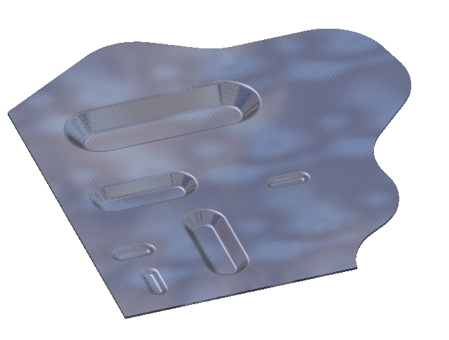
In this example a moulding tool for beadings is to be created. Processings by moulding tools are created in two steps: First, a (parameterized) sketch is used to create a subtraction on the sheet: Then, an (also parameterized) part is inserted an added to the sheet.
To define your own moulding tool, you need to take the following steps:
A completed model drawing showing both the result of Steps 1 and 2 as well as a finished sheet can be found in the drawing file FORMWERKZEUG_BEISPIEL.SZA. If you have installed a local version of the Help, you can also find this model drawing in the docu\examples folder.
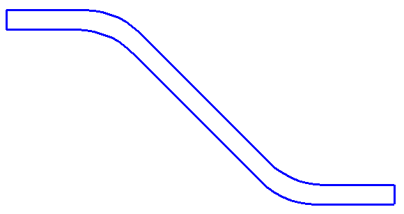
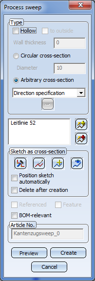
The part used for the processing is created as a C-edge sweep from a parameterized sketch.
 .
.
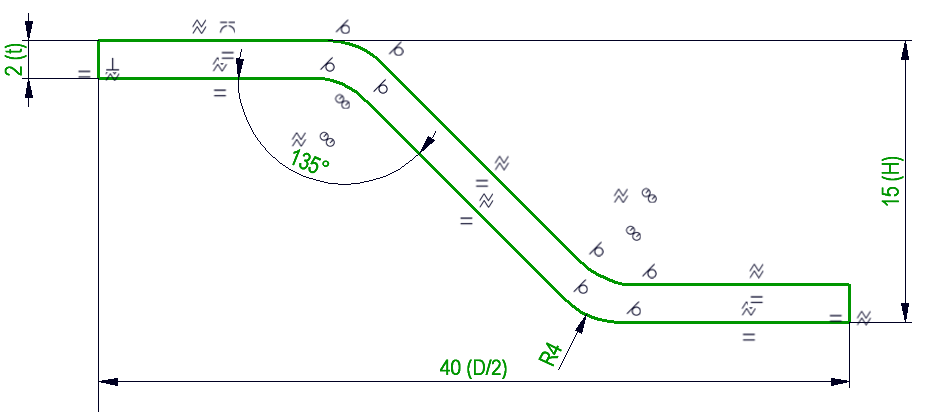
Through the positional constraints the sketch is completely defined. The utilized variables have the following meaning: t stands for the thickness of the sheet to be processed. h stands for the height of the beading, and d for the width.
! in the origin and is placed, by means of coincidence and distance constraints, relative to the origin.
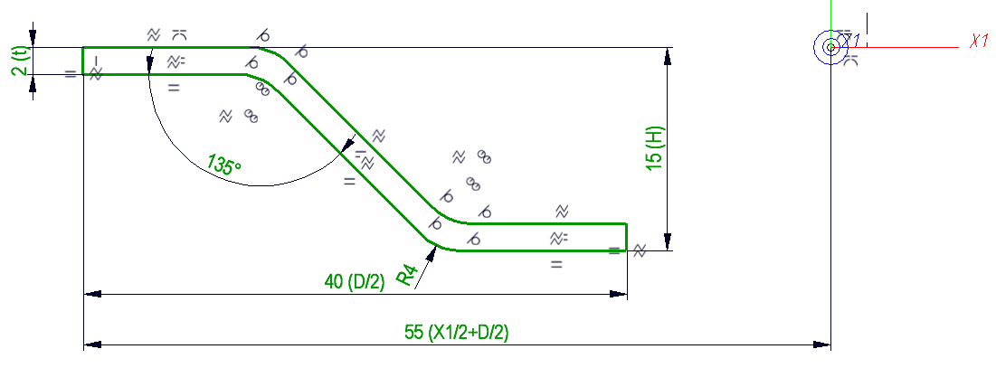
Perpendicular to this sketch, another sketch is now created, as a guideline for the C-edge sweep:
Here, the variables d for the width of the beading and x1 for the length are used again.
Now, the first sketch is used as a cross-section and the second sketch as the guideline of a C-edge sweep:
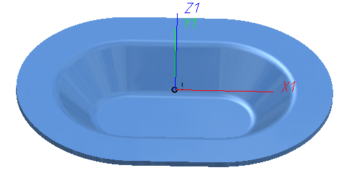
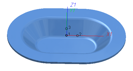
The actual processing has now been completed. Now, 3 named points must be specified according to which HiCAD will later determine the orientation of the processing:
One point with the point number 1 in the origin; one point with the point number 2 which, together with point 1, will represent the X-axis, and a point with the point number 3, which defines the orientation of the Y-axis.
 > New point
  .Use point option
  0 0 0 to place the point in the origin. Choose 3-D Standard > Tools > Point > New point number
  , identify the point that you just created and assign point number 1 to it.
Save the part.
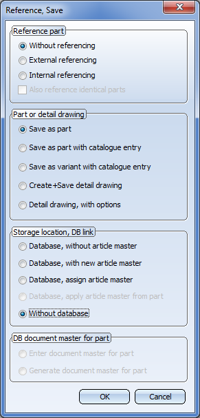
 . Specify the options in the dialogue window as shown below and confirm with OK.
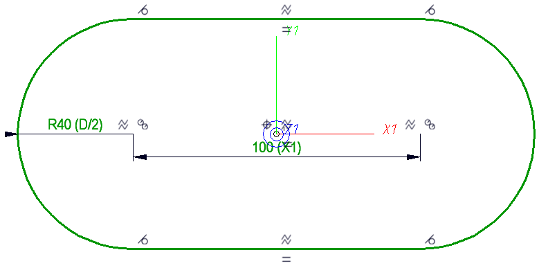
The sketch for the subtraction is readily available, allowing us to reuse the guideline of the C-edge sweep:
. In the dialogue window, choose the options Without referencing, Save as part and Without database. Confirm with OK.
 in the HiCAD EXE directory.
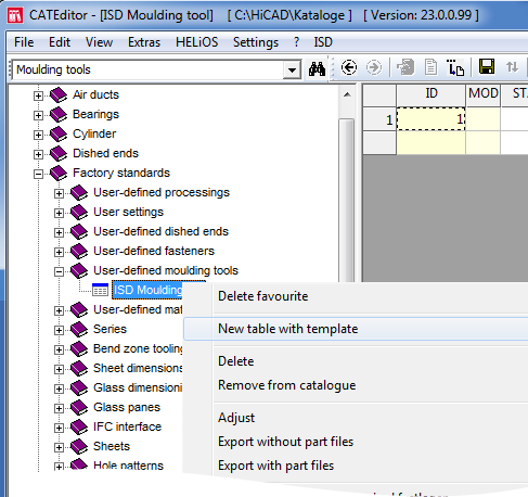
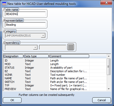
The created new table will then be displayed.
At this point, additional columns for the variables x1, d, h and t must be created: To do this, right-click on the column header at the far right and choose New column. Enter the parameter name in the Designation field, and Floating point number in the Data type field. If desired, you can enter an additional Comment in the same-named field.

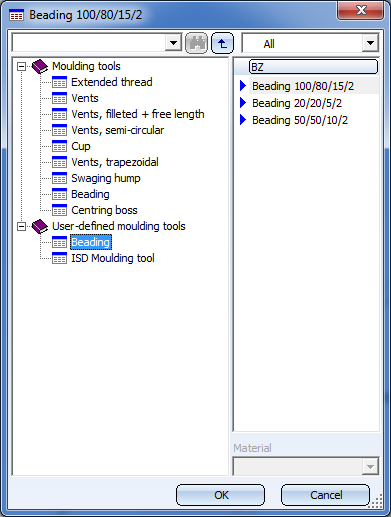
After creating the new table, close and restart HiCAD for the changes to take effect.
After restarting HiCAD the new Beading tools will be available to you:

|
© Copyright 1994-2019, ISD Software und Systeme GmbH |