
Project: HiCAD Plant Engineering
Plant Engineering > Isometry / Pipe Spool Drawing > Pipe spool drawing settings 
Isometry+Pipe Spool Drawing > Settings 
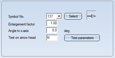
On the Symbols tab you define the appearance and size of north arrows, down-grade symbols, flow direction arrows and symbols for heating, cooling or insulation.
 Please note:
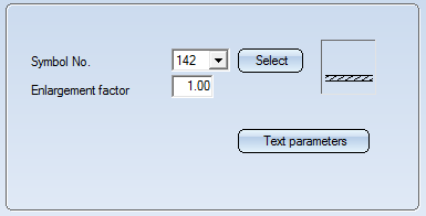
First, select from the list box which symbol settings you want to specify. The following options are available:


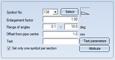

Clicking the Attribute button opens a dialogue window where you can combine text keys and database attribute into one text.
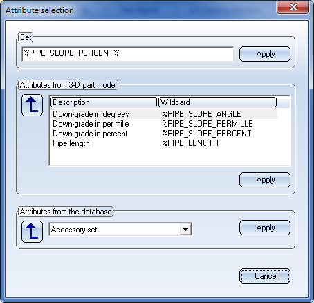
Select the desired text key and/or attributes and click the Apply button in the corresponding area. The Set field will then be updated accordingly. Click Apply to take over the text as displayed there.
Please note that the text key will be evaluated without a unit of measurement. If you want the unit of measurement to be output as well, you need to explicitly specify this in the text, e.g.
%PIPE_SLOPE_PERCENT%
The evaluation will then return, for example, 5%.
The representation of the text can be specified in the Text parameters dialogue window, that you open by clicking the same-named button.
Further setting options for down-grade symbols can be found in the Configuration Editor, at Plant Engineering > Isometry and Pipe spool drawing .
Down-grade symbols can only be set on straight pipes and straight sections of bent pipes.
 Interactions between rise triangles and down-grade symbols
Generally, down-grade symbols will suppress rise triangles. This means that no vertical rise triangle will be placed at a pipe section that has a down-grade symbol. If, though, the route of the section has an offset relative to the coordinate axes, a vertical rise triangle can still be created (provided that the corresponding setting has been specified.

A pipeline isometry provides a symbolic representation of the composition of a pipeline. In most cases, this pipeline is part of a larger plant in the layout plan. Within this layout plan there are other pipelines or components that are adjacent to the pipeline viewed in the isometry. Portions of these adjacent pipelines and components can be indicated to provide the observer with additional information on the pipeline environment.
Select the Connected elements entry to specify, separately for pipelines and components (e.g. vessels and pumps), whether and how exact their representation should be. You can switch off the indicating of Pipelines and Components by deactivating the same-named checkboxes.
Use the checkbox Pipe clamps of other pipelines to specify whether multi-pipe clamps are to be indicated or not. The checkbox is activated by default.
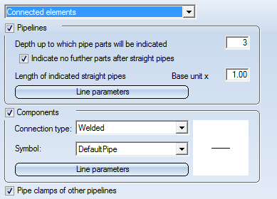
For pipelines you can specify the Depth up to which pipe parts will be indicated (seen from the connecting point) in the representation. The "depth" of a part results from the number of parts lying between this part and the connecting point. If it is directly attached to the connecting point, the depth will be 1. Weld gaps are not counted.
If you select the Indicate no further parts after straight pipes option, the parts that follow after straight (and also bent) pipes will not be shown. This makes sense as straight pipes normally represent a longer pipeline section.
For the same reason, straight pipes are not represented in their full length, but in shortened form. The length of the representation can be set in the input field for the Length of indicated straight pipes option. The Basic unit to which it refers unit is the same as for the pipe shortening, i.e. it is determined from the existing parts. As one can imagine, the unit of measurement will usually be the length of a symbol or the radius of an elbow. For bent pipes, only the first bend (or the first straight section) will be indicated.
The Line parameters option determines the actual representation, i.e. colour and line type.
In contrast to pipelines, components have no symbolic representation that could be used. Therefore, symbols depending on the type of the connection are used in the isometry. One can distinguish between 5 connection types, namely:
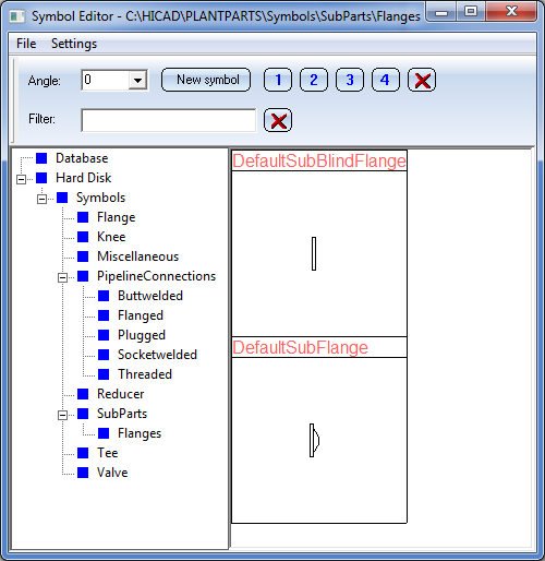
In the settings you can select one Symbol for each connection type. This symbol will be shown on the right area. The symbols are located in the PlantParts\Symbols\PipelineConnections directory of the HiCAD installation. This directory contains 5 sub-directories, one for each connection type:
| Buttwelded | Butt-welded | |
| Socketwelded | Socket-welded | |
| Threaded | Screwed | |
| Plugged | Plugged | |
| Flanged | Flanged |
Symbols located in these sub-directories are offered for selection in the Symbol list box. These directory structure can also be found in the Symbol Editor, enabling you to create new symbols if desired.
The Line parameters option determines the actual representation, i.e. colour and line type.
The JACOB pipe system offers pipe parts which already provide their own loose flange. This flange is conceived as a sub-parts to the actual pipe part. It is not shown in the symbolic representation of the pipe part, but its existence is indicated in the connection ID. You can define a symbolic representation for such sub-part flanges, which will be inserted at a suitable position in the isometry.
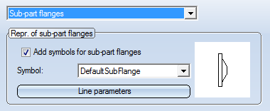
Add symbols for sub-part flanges
Use this checkbox to switch the generation of sub-part flanges on or off.
Symbol
Here you can select a symbol for the representation of the sub-part flanges. The selection box contains all symbols contained in the PlantParts\Symbols\SubParts\Flanges directory of your HiCAD installation. These symbols can be edited with the Symbol Editor. New symbols can be added as well.
Line parameters
A click on this button activates the line parameters dialogue window. There you can specify the colour, line type and the layer for the displaying of the sub-part flanges.

Settings (PE/Iso) • Isometry and Pipe Spool Drawing (PE/Iso) • Isometry/Pipe Spool Drawing Functions for the Layout Plan (PE)
|
© Copyright 1994-2019, ISD Software und Systeme GmbH |