Project: HiCAD Plant Engineering
Plant Engineering > Isometry / Pipe Spool Drawing > Pipe spool drawing settings 
Isometry + Pipe spool drawing > Settings 
Use the setting options on the Automatic dimensioning tab to specify the pre-settings for the automatic dimensioning.

If you want to dimension the arcs of bent pipes to facilitate processing on bending machines, activate/deactivate the desired checkboxes in the Draw angular dimensions area at the bottom left.
The dialogue window consists of the following areas:


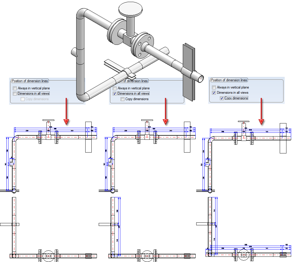
(1) Dimension line distance of 1st dimension line, Determine reference line... checkbox is active; (2) Dimension line distance of further dimension lines, (3) Dimension line distance of 1st dimension line, Determine reference line... checkbox is not active
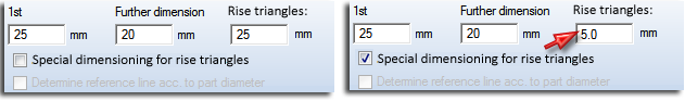
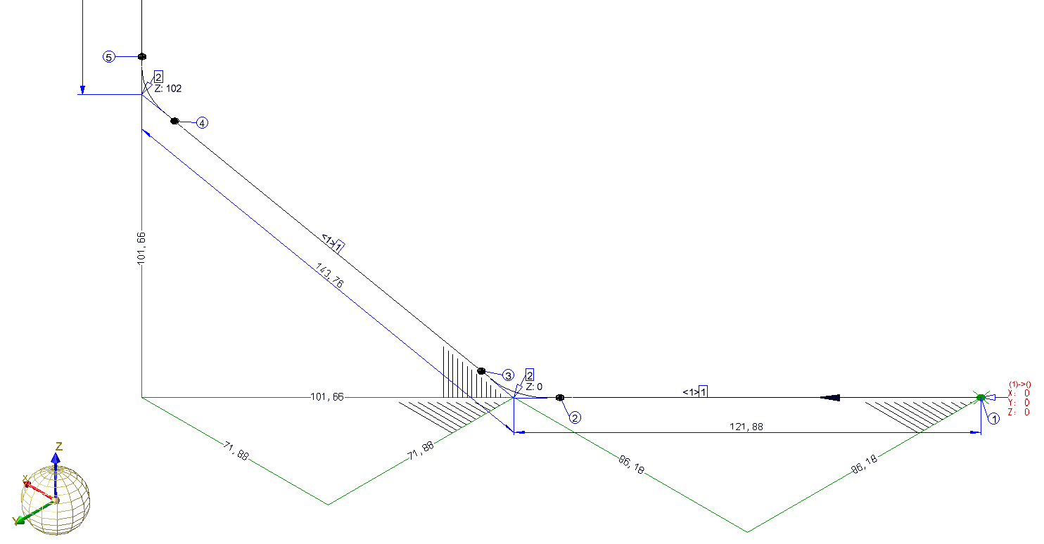
To avoid this, HiCAD offers the option to place only dimension figures (instead of complete linear dimensions) next to the edges of rise triangles. To do this, activate the Only write dimension figure next to rise triangles checkbox.
Linear dimensions on rise triangles - No special dimensioning for rise triangles
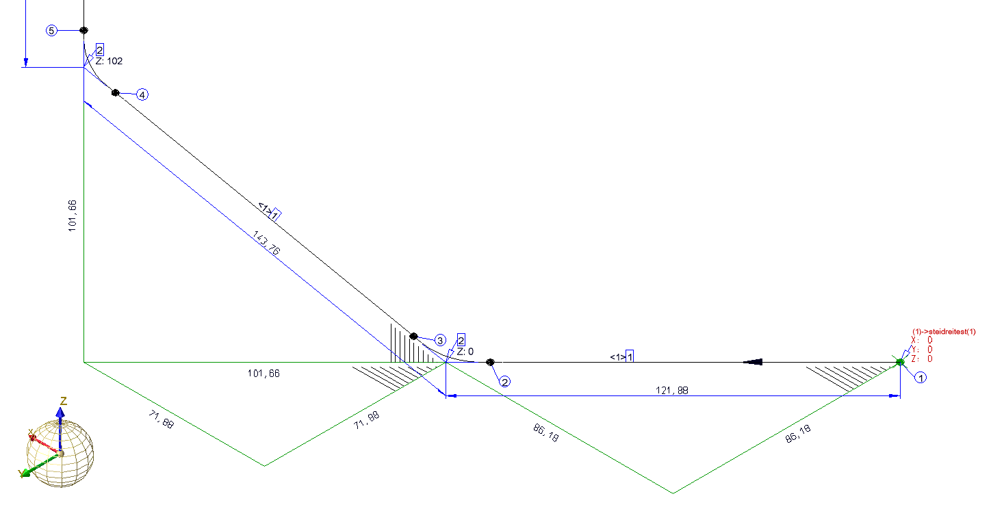
When the linear dimensions are removed, the dimensioning of the rise triangles is much clearer, and the overall view is less confusing. The dimension figure is placed centrally next to the relevant edge. The distance to this edge can be entered as a separate dimension distance into the Rise triangles input field. If the distance is positive, the dimension figure will be placed outside of the rise triangle, if the distance is negative, the dimension figure will be placed inside of the rise triangle. If the value is 0, the dimension figures will be placed onto the relevant edge.
Rise triangles only with dimension figures
If the Only write dimension figure next to rise triangles checkbox is deactivated, linear dimensions will be used for the rise triangles, but with the dimension distance entered in the Rise triangles checkbox. If the checkbox is deactivated, and the same dimension distance is set for Rise triangles and 1st dimension line, the behaviour will be the same as in older HiCAD versions (before HiCAD 2100.0).
Amongst other things, pipeline isometries in the Plant Engineering module serve the purpose of visualizing complex, three-dimensional pipeline constructions in such a way in 2-D, that this visualisation still gives a good impression of the spatial pipeline routes. If a straight pipeline does not run parallel to a coordinate axis, rise triangles can be inserted to convey a better impression of the spatial position of such a pipeline. Here, you distinguish between vertical and horizontal rise triangles:
For rise triangles you can specify, separately for vertical and horizontal rise triangles:
Concerning the hatching you can choose between the following two options:

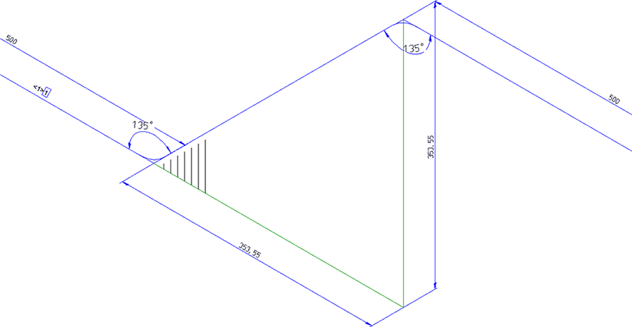
Vertical and horizontal rise triangle
If you select the Triangle surface area option for the hatching, the length of the corresponding hatching will be calculated by HiCAD accordingly. The effect of this setting is that an acute angle between hypotenuse and start cathetus leads to a longer hatching distance that an obtuse angle. Visually, the hatching in both rise triangles are equally intense. The result is a significantly enhanced impression of the three-dimensional course of the pipeline.
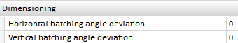
The vertical and horizontal hatching angles are automatically calculated to provide a best possible visual representation. However, if you prefer angles deviating from the automatically calculated angles, you can specify the desired difference angle in the Configuration Editor, at Plant Engineering > Isometry and Pipe spool drawing:
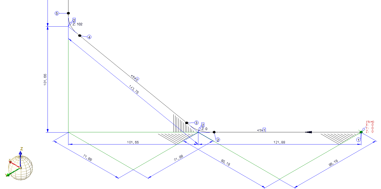
Offset triangles in front of pipelines if possible
If a straight pipe is not located in one of the three basic coordinates, you can, for the sake of a better spatial representation, insert two rise triangles:
If the two rise triangles overlap, the horizontal rise triangle will be mirrored (flipped) at its hypotenuse, thus avoiding an intersection. If a pipeline isometry has several areas with two rise triangles, the number of all overlaps of rise triangles will be determined in a first step. If more that half of the rise triangles overlap, all horizontal rise triangles in the complete pipeline will be flipped. The advantage of this procedure is that the cathetus between start point and base point of all horizontal rise triangles either runs in the direction of the positive Y-axis or in the direction of the negative Y-axis. Thanks to this consistent orientation, the observer does not need to re-orientate him/herself for each rise triangle and gets a better spatial impression of the situation.
 Interactions between rise triangles and down-grade symbols:
Generally, down-grade symbols suppress vertical rise triangles. This means that no vertical rise triangle will be placed next to a pipeline section that already has a down-grade symbol. If the route of the section has an offset to the coordinate axes, a horizontal triangle will still be created (provided that the corresponding setting has been set).
 These options are only available for isometries and not for pipe spool drawings!
Specify which dimensions are to be generated by activating or deactivating the corresponding checkboxes.
In (2) and (3), only parts with flange connections are individually dimensioned.
Besides the common functions for the dimensioning of angles on the 3-D Dimensioning + Text tab, you have the option to automatically generate the angular dimensions between the straight pipe segments of a bent pipe. For this to happen, activate the Angular dimensions checkbox.
The following image shows the dimensioning of two automatically generated angles:
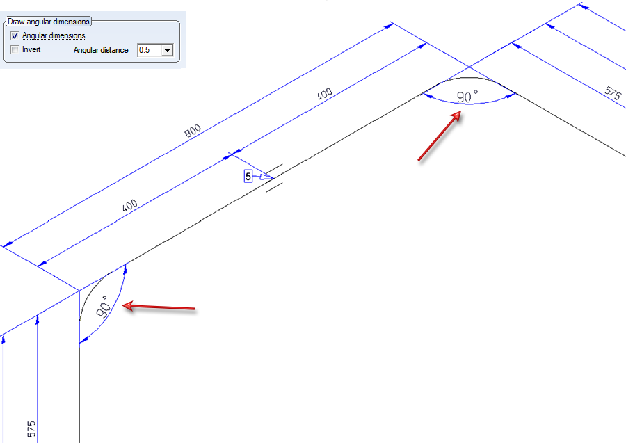
Use the settings beneath Draw angular dimensions to determine the distance and the orientation of the drawn angles.
Angular distance
This value determines the distance of the drawn angles to the intersection point of their legs.
Invert
You determine the orientation of the angular dimensions by activating or deactivating this checkbox, i.e. you determine whether the angle dimensions are to be drawn between their respective legs, or the opposite counter-angles are to be dimensioned. If the checkbox is active, the opposite counter-angles will be dimensioned.
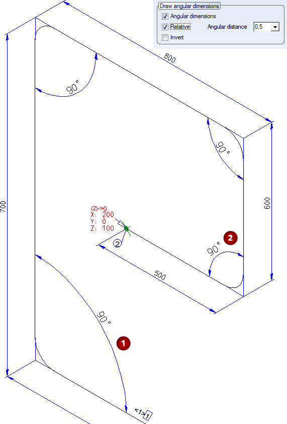
Relative
If this checkbox is active, the two pipe lengths of the adjacent legs are to be considered for the calculation of the distance of the angular dimension. The longer the two pipe segments of the adjacent two legs, the greater will be the extension of the angular dimension. This means: The longer the pipes, the more space will be occupied by the angular dimension in the isometry.
In the following image the dimensioning has been created with the setting Invert. Here, all angles have an equal extension, irrespective of the length of the adjacent pipe segments.

In the next image, the settings Relative: YES and Invert: NO have been selected. Here, the angular dimensions for the longer pipe segments, e.g. (1) are larger than thoise for the shorter pipe segments, e.g. (2).
Please note:
If the angles to be dimensioned are not perpendicular, and the Rise triangles function has been activated, the dimensionings will still remain clearly visible, since the rise triangles are by default only implied by means of a hatching that does not overlap the angular dimensions. As a result you will obtain a clear representation of the bent pipeline in space, while the added angular dimensions will remain easily readable.

Settings (PE/Iso) • Isometry and Pipe Spool Drawing (PE/Iso) • Isometry/Pipe Spool Drawing Functions for the Layout Plan
|
© Copyright 1994-2019, ISD Software und Systeme GmbH |