Project: HiCAD Plant Engineering
It can happen that pipelines are not continuous, but broken down in two or three parts. In such cases the isometry inserts spacers at the interruptions of the pipeline with a warning symbol attached to them. In this way, all interruptions in the pipeline will be visualized.
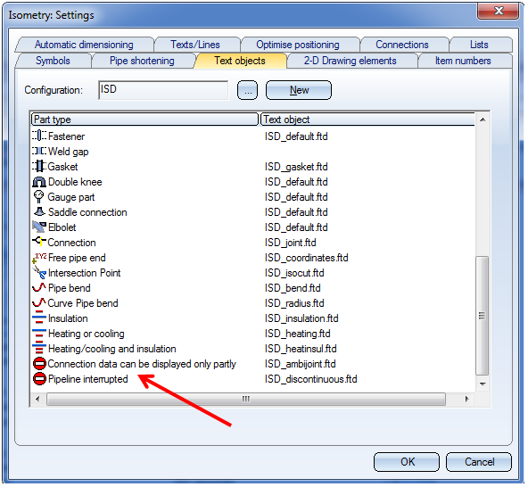
The text in the warning symbol is ~ by default. To change the text, call the Settings for isometry... function and open the Text objects tab.
Double-click the Pipeline interrupted list item and change the text as desired.
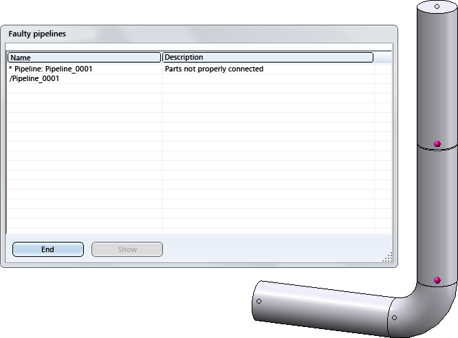
If you do not want to use spacers, open the Configuration Editor, select Plant Engineering > Isometry and Pipe spool drawing and deactivate the Create spacer for non-continuous pipelines checkbox.
If the checkbox is deactivated, HiCAD will issue a warning message if very small gaps between pipelines were detected.
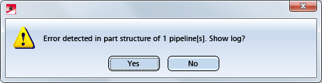
If you click Yes to show the log, all pipelines in which such connecting points were shown will be listed. At the same time, all these connecting points will be highlighted in the drawing.
If spacers are used, this warning message will be suppressed.
Click Show to highlight the pipeline that you selected in the list. The highlighting will remain as long as the error log is open, while navigating in the drawing remains possible.
This message will be suppressed if spacers are used.
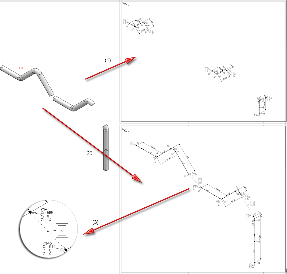
(1) Without spacers (up to HiCAD 2015), (2) With spacers, (3) Enlarged detail


Settings (PE/Iso) • Isometry and Pipe Spool Drawing (PE/Iso) • Isometry/Pipe Spool Drawing Functions for the Layout Plan
|
© Copyright 1994-2019, ISD Software und Systeme GmbH |