Project: HiCAD Plant Engineering
Plant Engineering > Isometry / Pipe Spool Drawing > Isometry settings
Plant Engineering > Isometry / Pipe Spool Drawing > Pipe spool drawing settings 
Isometry + Pipe spool drawing > Settings 
 The following description refers to isometries and pipe spool drawings.
Text objects have already been described in the Texts/Lines chapter.
|
(1) |
Example: Part item number with leader line and arrow, supplemented by nominal diameter specification for the T-piece; optionally, the Z-coordinate may also be specified here. |
|
(2) |
Example: Part item number on straight pipe |
|
(3) |
Example: Pipe bending information with leader line and arrow |
|
(4) |
Example: Weld seam item number with leader line, but without arrow |
|
(5) |
Example: Connection coordinates with leader line and arrow (can optionally be supplemented by additional text lines. The text will be asked for when creating the text object) |
You can save settings for text objects to part-specific, pre-definable configurations. Appropriate configurations are included in HiCAD’s scope of delivery.
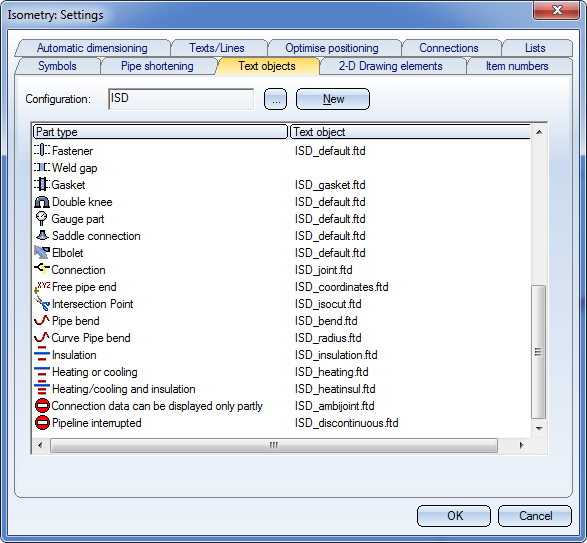

You can assign specific text object settings to each part type. These settings are taken from a corresponding FTD file. The FTD file assigned to a part type is saved to the -.FPA configuration file.
The ISD.FPA configuration file is included in HiCAD’s scope of delivery. This file is automatically loaded the first time you call the Text object tab. The corresponding FPA files (beginning with the prefix ISD_) belonging to this FPA file are stored in the MAKROANL sub-directory of your HiCAD directory.
Create new FPA files
Click New to create a new FPA file. The Create configuration window is displayed.
Enter a name for the new configuration file in the Designation field. Select the appropriate option button to specify how you want to create the file:
Example:
You can load another configuration by clicking the  button next to the Configuration field and select the required FPA file.
You can assign specific text object settings to each part type. These settings are taken from the corresponding FTD file.
To change the settings of text objects assigned to a part type, double-click the name of the corresponding FTD file. HiCAD then displays a dialogue box showing the settings saved to the file. You can handle the dialogue in the same way as the dialogue for 3-D annotation settings.
You can specify the number of post decimal places for text objects of isometries. The specification refers to the current line of the text object definition. It is therefore possible to display several values with different degrees of exactness in multiline text objects (e.g. x-/y-/z-coordinates in separate lines). If old settings (i.e. before version 2008) are loaded, this field remains empty. In this case, 2 decimal places are displayed.
Necessarily incomplete representation of a connecting point
At connecting points, information are displayed, for example, via the connection symbol. In the isometry presettings, for example, connecting points which have already been realised in the factory are represented by a black, filled circle, and connections which still need to be realised on a site are represented by a green, filled circle with a cross.
At multiple branchings, several types of connections can converge, which means that they cannot be represented by one single symbol. In such cases, an additional annotation tag will be attached at this connecting point - in the isometry as well as in the pipe spool drawing. The images show a branching point where a saddle connection mounted in a factory has been attached. A pipe to be mounted on a site has to be attached at exactly the same point.
What exactly will be displayed in the text field of the annotation tag is determined by the FTD file specified under Display connection info only partly. The following FTD files have been predefined by the ISD:

Settings (PE/Iso) • Isometry and Pipe Spool Drawing (PE/Iso) • Isometry and Pipe Spool Drawing Functions for the Layout Plan (PE)
|
© Copyright 1994-2019, ISD Software und Systeme GmbH |