
Project: HiCAD Plant Engineering
Plant Engineering > Isometry/Pipe Spool Drawing > Auto-generate drawing
Plant Engineering > Isometry/Pipe Spool Drawing > Generate pipe spool drawing 
Isometry + Pipe spool drawing > Create > Auto-generate drawing 
All pipelines in the current drawing are listed on the left side of the Plant Engineering Isometry dialogue window, and the checkboxes are active (unless the function was called via the context menu. In this case, only the checkbox of the current pipeline will be active.
Furthermore, all pipelines in the current drawing are listed on the left side of the Pipe spool drawing dialogue window. Here, only the checkboxes of the pipelines belonging to the previously selected parts are active.
Select the pipeline you want to process. You have the following options:
Select the desired pipelines via double-click on the corresponding list item.
Click on this button to select the desired pipelines in the drawing. Right-click to get back to the dialogue window.
Click on the button to select or deselect all pipelines in one step.
HiCAD offers the option to combine several pipelines into a set, which will then be regarded as "one" pipeline when generating the isometry or the pipe spool drawing. Since you can freely define such pipeline sets, you are enabled to separate you model drawing into pipelines in a more flexible way and without having to have the drawing generation already in the back of your mind.
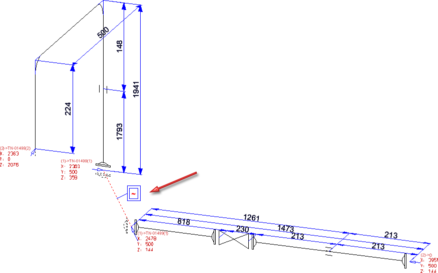
The decisive difference between the drawing of a pipeline set and the drawing of a separate pipeline is that the points where the pipelines of a set converge will be interpreted as inner points of a pipeline. Chain dimensions span these points and connecting points are marked accordingly; no annotation tags with connection coordinates will be created.
In an isometry, attention is paid to the question whether the set is continuous. If required, distance elements will be created and marked with by a tilde ~:
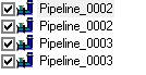
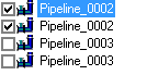
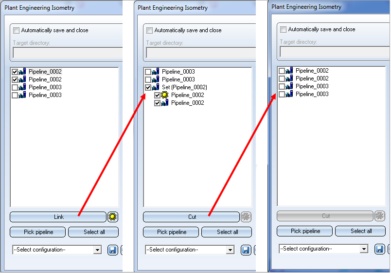
To define a pipeline set, simply select the pipelines you want to combine into a set and click on the Link button. The selected pipelines will then be merged into a set in the list, and will automatically obtain the name Set, followed by the name of the main pipeline in brackets, e.g. Set (Pipeline_0002).
The Link button is context-sensitive. When you select a pipeline set, the name of the "Link" button will change to Cut. Click the Cut button to split the set up into the individual pipelines again.
The main pipeline is marked with the  symbol. The purposes of the main pipeline in the isometry and pipe spool drawing are as follows:
You can use the  icon to make a different pipeline the main pipeline of the set.
![]() Please note:
Please note:
 , the following message will be displayed:

 function the use of pipeline sets is a flexible possibility to arrange isometries or pipe spool drawings appropriately.


Generate Isometry / Pipe Spool Drawing (PE/Iso) • Isometry and Pipe Spool Drawing (PE/Iso) • Isometry and Pipe Spool Drawing Functions for the Layout Plan (PE)
|
© Copyright 1994-2019, ISD Software und Systeme GmbH |