Project: HiCAD 3-D
3-D Standard > Clone > Param.
Use this function to copy ("clone") parts on a grid via
You can combine these different procedures with each other, creating more complex patterns in this way.
Let us assume that you want to clone a part on a grid - first by linear displacement, and then copy these clones once more via a rotatory pattern. With the Clone parts, parametric function you can achieve the desired result in one step.
When you call the function, the Clone part dialogue window will be displayed.
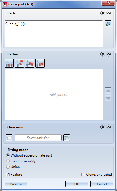
The dialogue window consists of the following areas:
|
Meaning of the symbols |
|
|---|---|
|
|
Expands and collapses input areas of the dialogue window. |
|
|
Expands only one area, i.e. the other areas will be collapsed. |
|
|
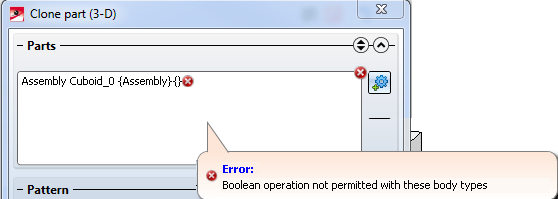
Indicates incorrect inputs. If you move the cursor over the symbol, you will obtain further information, e.g.:
|
|
|
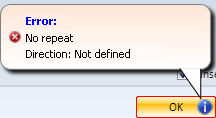
Indicates that mandatory inputs are missing. If you move the cursor over the symbol, you will obtain further information about the inputs that are still missing, e.g.:
|
During input of data, a semi-transparent preview of the clones based on the inputs in the dialogue window will be displayed in your drawing. Click on the Preview button to make the preview better visible. Click on the OK button to create the clones as shown in the preview.
 In the preview the original of the active pattern in the pattern list will be displayed in green, and the copy in red.

When you call the function, the currently active part or the active part list will be displayed. You can add further parts for selection by clicking on the Select part  symbol and choosing the part in the drawing or in the ICN. Already selected parts will be removed form the list when they are selected again. To delete parts from the list, you can also right-click and choose Remove element(s) from the list.
As long as the selection list is highlighted by a frame in the Special colour Marking 5 you can select parts without having to click on the .
Here you choose the pattern for the cloning. To select a pattern, click on its symbol and enter the required values.
As already mentioned, you have the option to combine different patterns here, e.g.:
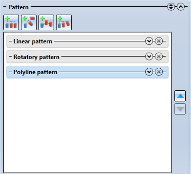
To remove a pattern from the pattern list, click on the corresponding  symbol.
The following patterns are available:
 Translatory + rotatory patterns.

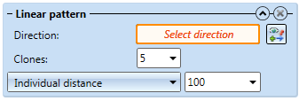
Use this function to create clones by specifying a direction vector.
Direction
You can choose any edge or a coordinate axis as the direction vector. To determine the direction, click on the  symbol and then define the vector by choosing an edge or by specifying a start point and an end point. You can also right-click to open a context menu with further functions for determining the displacement direction:
|
|
Origin
|
|
|
X-axis
|
|
|
Y-axis
|
|
|
Z-axis
|
|
|
Step back
|
|
|
Cancel
|
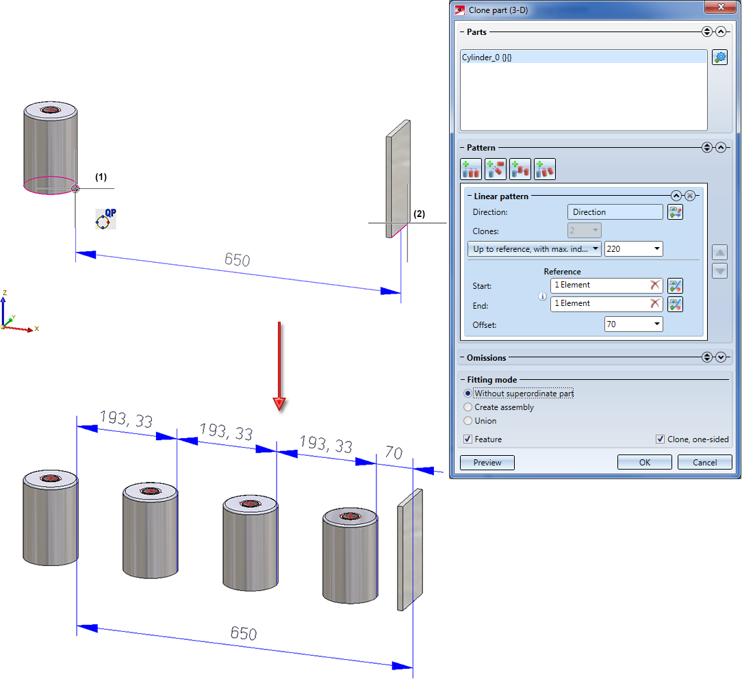
Clones
Enter the number of clones here. Please remember that the original will not be added to the number of clones here! If you wish to specify the number of clones in positive and negative direction, deactivate the Clone, one-sided checkbox in the dialogue window.
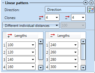
Distance
You have different options to determine the distance between the individual clones:
You can also determine several start and end references by clicking on the  symbol next to the corresponding input field and selecting the desired element. The number of the selected elements will be shown in the input field, e.g.:
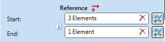
In this case, always the smallest distance resulting from the specified start and end references will be used. This distance can be shown by clicking on the  symbol.
If you select an already selected element again, it will be removed from the list of references. To remove all start or end references, click on the Delete symbol in the respective input field.
Please note:
If the chosen end reference for the distance options
is an edge, please note the following: If the straight line running through the start reference and in the cloning direction does not intersect with the end reference, the minimum distance of the straight line to the end reference will be selected automatically.

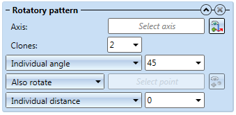
Use this function to clone the active part or part list with a rotatory pattern, i.e. through rotation about an axis.
Axis
An arbitrary edge or coordinate axis can be defined as the rotation axis. Click on the  symbol and define the rotatation axis by selecting an edge or by specifying the start point and the end point. You can also right-click to open a context menu with further functions for determining the axis , as you would do for the Direction of the linear pattern.
Clones
In this area you enter the number of copies. In contrast to other cloning functions, the original will not be added to the number of copies here. If you wish to specify the number of clones in positive and negative direction, deactivate the Clone, one-sided checkbox in the dialogue window.
Angle
The rotation can either be performed by specifying an angle, or fully symmetrical.
Also rotate / Fixed point
If you choose Also rotate, the clones will be also rotated along the rotation path. An alternative to this is Fixed point, where an additional path point needs to be specified via which the clones will be moved on the rotation path.
Individual / Total distance
The height of the copies relative to the original can be changed. In this way you can, for example, create patterns in the form of a spiral. The value of the vertical displacement can be specified as total or individual value. If you select the Total distanceoption, the specified value will be the displacement of the last copy relative to the original. This means that if you have , for example, selected 5 Copies and specified a Total value of 10, each of the copies will be vertically displaced by a value of 2. If you selected the Individual distanceoption, this value will apply for each individual copy.

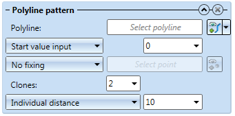
Use this function to clone the active part or part list along a polyline.
Polyline
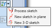
Both planar sketches and 3-D sketches can be used as polylines. Click on the  symbol and identify an edge of the sketch. If you click on
  you have the option to create a new sketch, or process an existing planar sketch:
Start value input / Start point selection
These options make sense if the part to be cloned is not located at the start of the polyline. In this case you have the option to consider the distance of the part from the polyline start by specifying a start value. You can either specify the start value by a start value input or by selecting a start point on the polyline. If you have selected the Start point selectionoption, click on the  symbol and specify the required point on the polyline.
Fixing
 symbol and define the vector by selecting an edge or specifying two points.
 Clones
Enter the number of clones here. Please remember that the original will not be added to the number of clones here! If you wish to specify the number of clones in positive and negative direction, deactivate the Clone, one-sided checkbox in the dialogue window.
Distance
You have the following options to determine the distance between the individual clones:
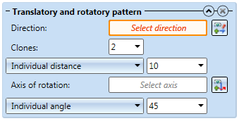
Use this function to clone the active part or part list with translatory and rotatory patterns.
Direction
You can choose any edge or a coordinate axis as the direction vector. To determine the direction, click on the symbol and then define the vector by choosing an edge or by specifying a start point and an end point. You can also right-click to open a context menu with further functions for determining the displacement direction.
Clones
Enter the number of clones here. Please remember that the original will not be added to the number of clones here! If you wish to specify the number of clones in positive and negative direction, deactivate the Clone, one-sided checkbox in the dialogue window.
Distance
You have different options to determine the distance between the individual clones:
Rotation axis
An arbitrary edge or coordinate axis can be defined as the rotation axis. Click on the symbol and define the rotatation axis by selecting an edge or by specifying the start point and the end point. You can also right-click to open a context menu with further functions for determining the axis , as you would do for the Direction of the linear pattern.
Angle
The rotation can either be performed by specifying an angle, or fully symmetrical.
 Example - Translatory + rotatory pattern
Here you have the possibility to omit individual copies, i.e. to suppress their generation. These can be selected either in the preview with the cursor or, by specifying the corresponding working step, entered into the table. Please note that the omission will apply globally, i.e. to the end result, and not to the individual patterns.
Die Symbole:

|
Table
|
|
|
Select omission
|
|
|
Add omission
|
When manually adding omissions in the table, the number of working steps (patterns) must be considered. The original always has the number 0 in the respective working step. If you have selected only one pattern, the clones will have the numbers 1, 2, 3 etc. In case of two patterns there will be number pairs: The first number, i.e. the input field 1, stands for the clone from the first pattern, the second numberin the input field 2 for the clone from the second pattern. For each further pattern, a column will be added to the table.
An example:
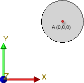
The image below shows an original, which is a cylinder with a height of 50 and a diameter of 15 in the top view.
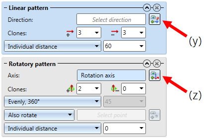
Now, choose Param... and define, in the first step, a linear pattern (Direction: Y-axis) and, in a second step, a rotatory pattern (Rotation axis: Z-axis) with the settings as shown below.
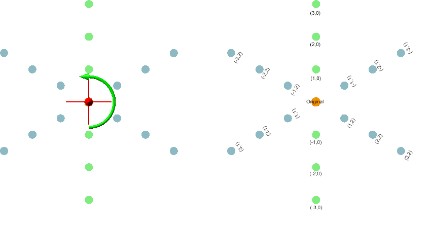
The image on the left shows the preview of the cloning. The image on the right shows the number pairs of the individual clones for the sake of illustration.
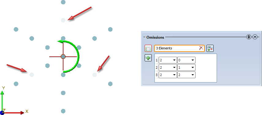
So, if you want to omit the following elements, the table must look as shown below:
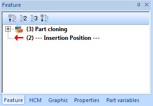
Here you determine how you want the clones to be inserted. You have the following options:
 When you select this option, a superordinate part or assembly needs to exist. if the Feature checkbox is active, the Part cloning feature will be assigned to the superordinate part or assembly. For instance, if you have cloned an assembly that is a sub-assembly to a main assembly, the feature will be assigned to the main assembly.
  symbol. When you move the cursor over the symbol, you will obtain further information.
Beispiel - Kombination von Mustern
Please note:
When you have activated the Feature option, you can add further patterns to a parametric cloning. Just double-click the Part cloning feature to start the function dialogue anew.

Transform + Clone Part (3-D) • Transform Part (3-D) • Referencing (3-D)
|
© Copyright 1994-2019, ISD Software und Systeme GmbH |