"Civil Engineering" docking window" > Steel Engineering > Stairs+Railings > Stairs > Staircase Configurator
Use the new Staircase Generator to create single-flight, straight stringer staircases with intermediate platforms - with or without utilisation of stairwell contours. Individual settings, such as various stringer or step variants, as well as various connection options for stairs to stringers, or the definition of standardized platforms are available.
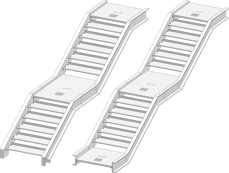
Left: Staircase with entrance stringer as pillar, intermediate and landing platform; Right: Staircase with entrance, intermediate and landing platform
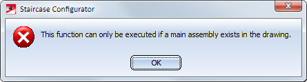
A prerequisite for the start of the Staircase Configurator is that the current drawing contains a main assembly. If this is not the case, a corresponding message will be displayed.
Extensive information on main assemblies can be found in the topics
Assemblies, Main Parts and Sub-Parts,
Part Drawing or Assembly Drawing and
Edit Part/Assembly Structure .
After calling the Staircase Configurator, HiCAD will prompt you to identify the stairwell, or to press the middle mouse button if you want to work without stairwell.
Working with stairwell contours
Here you fit the staircase into a stairwell. For this to happen, a suitable sketch for the stairwell must exist in your drawing. This sketch serves the purpose of positioning the staircase in the stairwell and defining the stair start (the so-called "entrance"). Therefore, the first step will be creation of a stairwell with the help, of the functions on the Sketch tab.
The length of the stairwell must not be smaller than the total length of the staircase. If this is the case, HiCAD will display an error message.
Identify the sketch in the vicinity of the stair start.
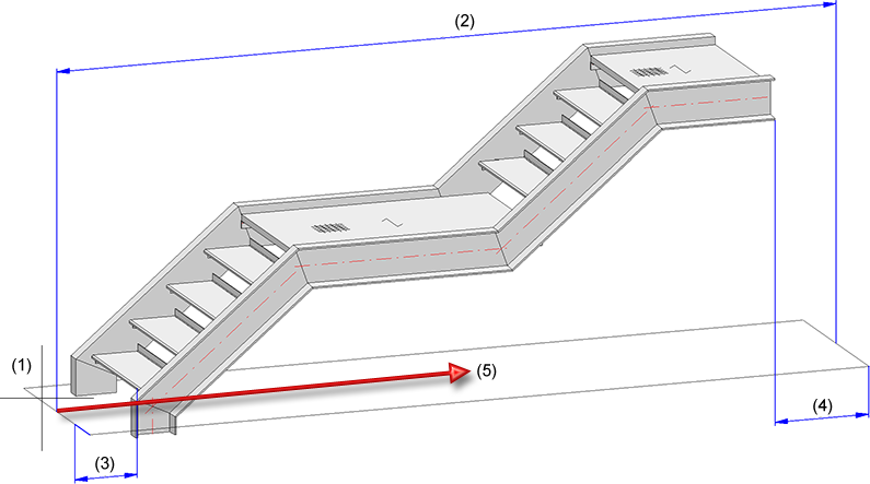
(1) Identified sketch, (2) Sketch length, (3) Distance at stair start, (4) Distance at stair end, (5) Walking direction
If you work without a stairwell contour, the fitting point of the staircase will be placed in the origin of the World Coordinate System. You can freely select this fitting point when you insert the staircase.
The input fields of the Staircase Configurator dialogue window will always be initialised with the last saved values when you open it to create a new staircase.
The window consists of the following tabs:
Specify the desired staircase parameters on the tabs.
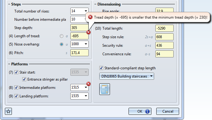
Click OK to start the staircase generation. HiCAD will check first if the staircase can actually be constructed according to the entered parameters If this is not the case, the  symbol will be shown on the OK button. In the dialogue window, fields with an incorrect value will be marked with the
  symbol. Move the cursor over the symbol to obtain further information, and correct the staircase parameter.
If the check was successful, HiCAD starts with the staircase generation. The current status of the generation will be indicated by a progress bar at the bottom of the window. A feature called Stairway will be entered in the Feature log.
Working with Favourites
The settings specified in the dialogue window can be saved as favourites and re-used at any time if desired. To do this, click the  symbol at the bottom left of the dialogue window.
More information on favourites management can be found in the Manage Favourites topic of the HiCAD Basics Help.

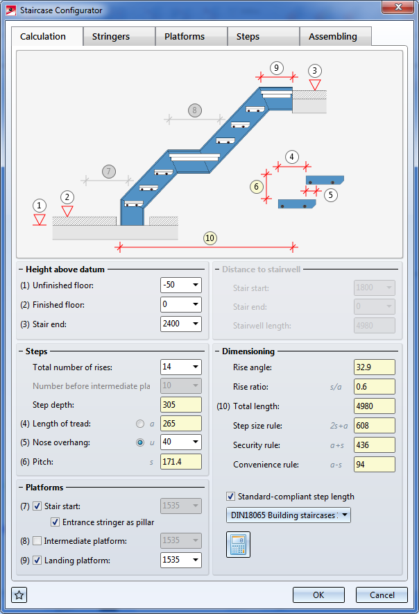
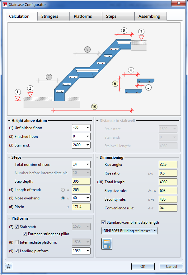
On this tab you specify the size of the staircase, the number of steps and platforms.
The values beneath Dimensioning, i.e.
will be automatically calculated on the basis of the specified staircase parameters.
The Staircase Configurator will observe the calculation rules for staircases:
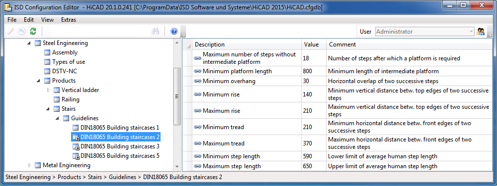
If you want to ensure a standard-compliant step length for the staircase, activate this checkbox. You can then select the design guidelines to be observed from the listbox below. These guidelines, e.g. national regulations, are determined in the Configuration Editor, at Steel Engineering > Products > Stairs > Guidelines. The ISD has predefined the guidelines according to the industrial standard DIN 18065. To define further guidelines, right-click on one of the guidelines on the left hand side and select Derive structure.
 Determine optimal stair parameters
If you click on this icon, HiCAD will use the entered staircase data to check whether the step length is standard-compliant, and whether the selected guideline is kept to. If this is not the case, the values will be automatically corrected and will be highlighted in red. The inputs can, however, still be edited.
To place the cursor in a particular input field, you can also click on the corresponding markers in the graphic of the dialogue window. If, for example, you click on the marker in the graphic of the Calculation tab, the cursor will be placed in the Unfinished floor input field.
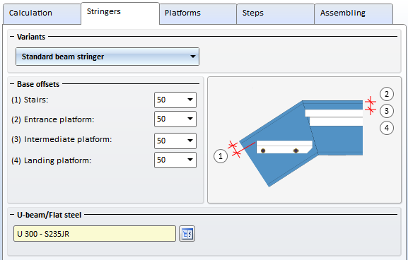
On this tab you can specify the stringers to be used for the staircase.
First select the variant:
Then, enter the base offsets for platforms and stairs.
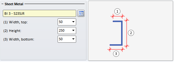
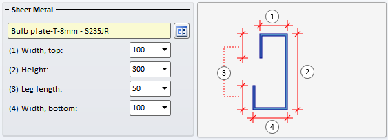
Select - depending on the selected stringer variant - the beam or the plate/sheet from the HiCAD catalogue by clicking the  symbol. In the case of Sheet Metal stringers you need to specify the parameters Width, top (1), Width, bottom (2) and Height (3).
If you use Sheet Metal U stringers, specify the desired values for Width, top (1), Height (2) and Width, bottom (3).
If you use Sheet Metal C stringers, specify the desired values for Width, top (1), Height (2), Leg length (3) and Width, bottom (4).
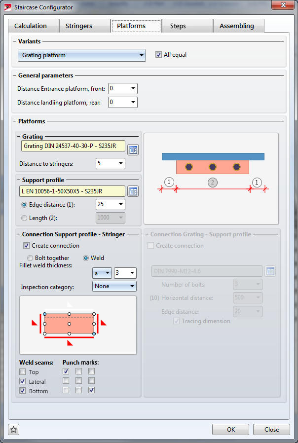
Here you specify the data for the entrance, landing and intermediate platform.
Specify the distance of the entrance platform at the front, and the landing platform at the rear. If you want to use the same data for different platforms, activate the All equal checkbox.
Grating
Currently only grating platforms are available. Click the symbol and select the desired grating from the catalogue. Enter a distance to the stringers.
Support profile
Select the support profile from the catalogue by clicking the symbol, and specify its size - either by entering the edge distance or the length.
Connection Support profile - Stringer
Activate this checkbox if you want to create a connection between support profile and stringer. You can choose between a bolted and a welded connection.
Connection Grating - Support profile
If desired, proceed likewise to specify the bolted connection between grating and support profile .
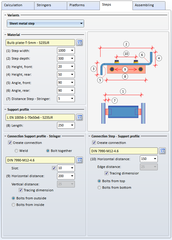
Here you specify the data for the stair steps.
Variants/Material
Select the desired variant and enter the required data.
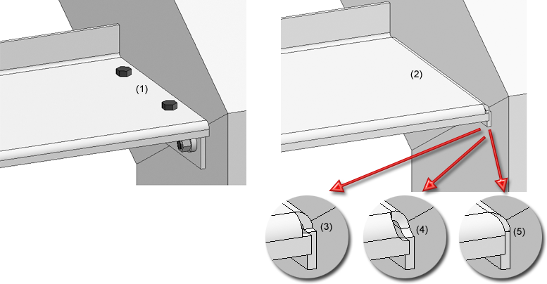
(1) Sheet Metal step, (2) Sheet Metal step without support profile - Corner processing: Rectangular cut-out (3), Circular cut-out (4), Closed (5)
Support profile
Select the support profile from the catalogue and specify its length.
Connection, Stringer
If you want to create a connection between support profile and stringer, activate the corresponding checkbox. You can choose between a bolted or a welded connection. Please note however that bolted connections are only possible for particular support profiles, e.g.for L-beams.
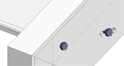
Connection, Step
If desired, proceed likewise to specify the bolted connection to the step.
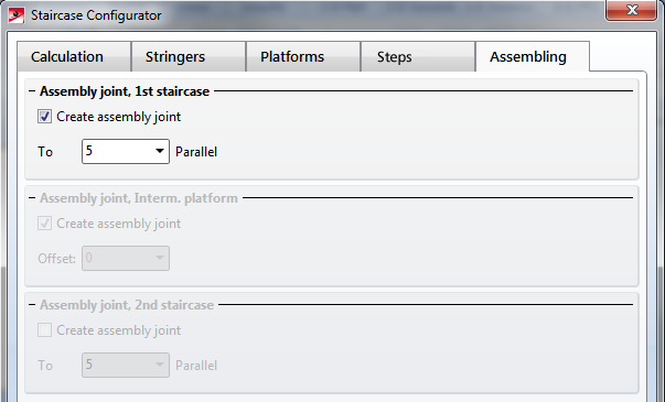
On this tab you specify whether (and which) assembly joints between staircase sections are to be created.
One distinguishes between:
Boltings can be installed as loose parts or be assigned to the assembly of the respective level. Activate the desired option. When installing them as loose parts the bolting connections will be assigned to the Accessory Parts assembly.

Staircase Configurator - Important Notes (3-D SE) • Stairs and Railings (3-D SE) • Sketch (3-D)
|
© Copyright 1994-2018, ISD Software und Systeme GmbH |