Steel Engineering > New > Insert new standard beam 
This insertion type enables you to insert the beam into the currently active processing plane. This is the default setting if none of the other insertion types is active.
This option then provides the following ways of inserting the beam:
|
|
Insert with sketch |
Sketch technology is used to insert the beam. From the start point, HiCAD automatically fades in auxiliary lines along a predefined grid and displays the relevant angles and distances at the cursor. On this grid, you can then click the mouse, for example, to define the direction and length of a line by means of corresponding cursor movements. |
|
|
Insert via point and length |
The beam is inserted by defining the start point and specifying a point in longitudinal direction of the beam.
|
|
|
Insert via 2 points |
The beam is inserted by specifying the start and end points. The position of the beam is defined by the start point, length and direction by the end point. If this option is active, the input field for the length is blocked.
|

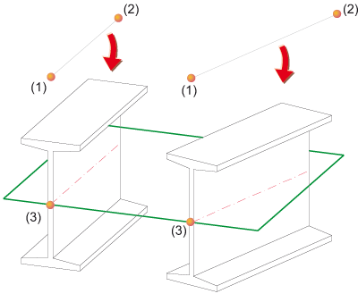
Insertion in plane
|
Left: |
Right: |

Insertion Options for Beams and Profiles (3-D SE) • Insert Beams (3-D SE) • Steel Engineering Functions
|
© Copyright 1994-2018, ISD Software und Systeme GmbH |