
Grids are often used as construction aids, especially in Steel Engineering. You can refine the structure of 3-D and Steel Engineering grids further by defining different grid sub-systems for each plane of the grid. These grid-subsystems can also run diagonally within the grid planes.
A grid sub-system has a start point and an end point, and is represented as a line. The grid and its sub-systems are normally shown in the Model area, to enable a designing along the grid lines.
Grid sub-system 
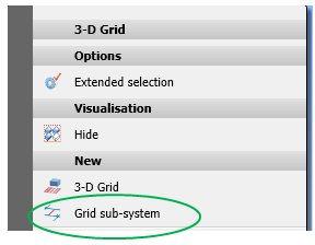
To define a grid subsystem, right-click the grid and select the Grid sub-system function from the context menu.
After calling the function you will be prompted to specify the start point and the end point of the grid sub-system. During the process of point specification you can right-click to open another menu with further options:

You can then either end the function, or remove the previously specified start point and specify a new one.
The grid sub-system that was defined by the two specified points will be inserted in the grid plane as an edge. You can then define further sub-systems, or end the function.
Grid sub-systems are inserted as sub-parts with the name Sub-system, arranged within an assembly called Grid sub-system. This main part will in turn be assigned to the grid that is active when the function is selected.
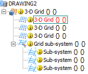
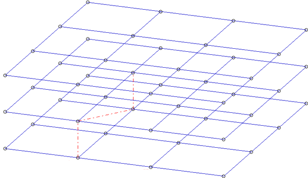
Grid with 3 planes and 3 sub-systems (red dash-dotted line)
![]() Please note:
Please note:
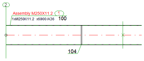
Grid annotation tag (left) and grid sub-system annotation tag (right) in derived drawing
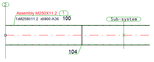
Grid annotation tag (left) and grid sub-system annotation tag with name(right) in derived drawing
To apply changes to grid sub-systemsyou can use many of the normal processing functions for parts:

Grid Annotation (3-D SE) •Settings/Management (3-D SE) • Steel Engineering Functions
|
© Copyright 1994-2018, ISD Software und Systeme GmbH |