Steel Engineering > Further functions > Settings  > 3-D Grid
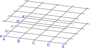
Using a steel engineering grid is particularly recommended if several beams located in the same plane need to be fitted. Examples include stages, bridge frames, substructures for car parks, roof constructions etc. When specifying the start and end points of the beams, you can then access the grid points directly, which speeds up fitting.
The Grid dialogue window is displayed to enable you to configure steel engineering grids.
|
Options and Buttons |
|
|---|---|
|
Number |
Number of grid lines in x-/y-direction |
|
Distance |
For even axis distances, enter the distance between the axes in the Distance field. If you want unevendistances between the axes you can enter the values directly into the table on the right-hand side of the window. |
|
Axis annotation |
You can specify the start value for consecutive axis annotation here. If you do not want the annotation to be consecutive, you can also enter the axis annotation directly into the table on the right-hand side of the window. |
|
Planes |
Steel engineering grids can consist of several planes. Specify the number of planes and the distance between each of the planes. |
|
Projection |
This value specifies how far the grid lines project beyond the border of the grid. |
|
Text parameters |
Click this button to define the text parameters for the axis annotation. |
|
Save |
Saving the current grid settings. The data is saved in the HiCAD subdirectory Makro 3-D/Raster under the specified name with the extension .RST. The RST files can be reused at any time – even for other steel engineering constructions. |
|
Load |
Loading a saved 3-D grid (.RST). |
After specifying the required grid settings, choose OK to exit the window. HiCAD displays a preview of the grid.

Steel Engineering grid with 2 planes
![]() Please note:
Please note:
 .
.  function to assign user-defined annotations to individual axes of the grid. Please note that changes of the grid , e.g. the parameters, may also influence system axis annotations.

Grid Annotations (3-D SE) • Settings/Management (3-D SE) • Steel Engineering Functions
|
© Copyright 1994-2018, ISD Software und Systeme GmbH |