
Steel Engineering > Plate, new > Glass
You use this function to fit glass panes into frameworks. Fitting can be one-sided or two-sided. The prerequisite is for you to set glass points which define the glass thickness. Series beams are used to create the frame.
![]() Glass panes for non-closed beam frames can also be generated
automatically. Select Further functions > Settings
Glass panes for non-closed beam frames can also be generated
automatically. Select Further functions > Settings  > Glass insertion> End points to define how you
want the open ends to be closed:
> Glass insertion> End points to define how you
want the open ends to be closed:
 For glass insertion the default settings of the Default glass function are used. If it is not possible to use these settings, e.g. because the glass thickness determined by the glass points is too great or too low, the dialogue window Glass structure is displayed. Here you can either modify the values accordingly or define new glass panes.
Create series beams for frame
For the glass fitting to be carried out automatically, the cross-section of the series beam used must exist as a 2-D part (figure) or as a 2-D DXF file and fulfil certain prerequisites.
For automatic glass fitting, a sub-part GLASS which consists only of isolated points, i.e. the glass points, also needs to be created. These points define the glass thickness and the distance from the axis. Furthermore, you also specify the direction of the geometry shift for variable glass thickness
Unique point numbers need to be assigned to the isolated points for glass fitting. For one-sided glass fitting, glass points 10,11,12 need to be defined; for two-sided fitting, glass points 20,21,22 need to be defined in addition. Please make sure that you keep to this designation, as HiCAD cannot determine the glass points otherwise.
Procedure
2-D figure with glass points (1) for a Forster series beam (extract)
Fit glass to frame
If a closed frame of series beams with glass points exists, you can use the Glass insertion function to start the glass fitting automatically.
The glass is inserted into the part structure as a main part with the article number (designation) GLASS nn, where nn is the glass thickness which is defined by the glass points assigned in the 2-D figure.
The figure shows a frame of Forster series beams, to which the glass
has been automatically fitted.
Left: Frame with automatically fitted glass, Right: Extract of glass in the frame (Forster beam)
Please note:
> Glass insertion > Default glass. 
Steel Engineering > Plate, new > Glass > Glass from sketch 
![]() Please note:
Please note:
The old Glass from sketch function will still be temporarily available as Glass from sketch (old).
Use the Glass from sketch function to derive single or multiple glazings from sketches in a model drawing.
When you call the function, the following dialogue window will be displayed:
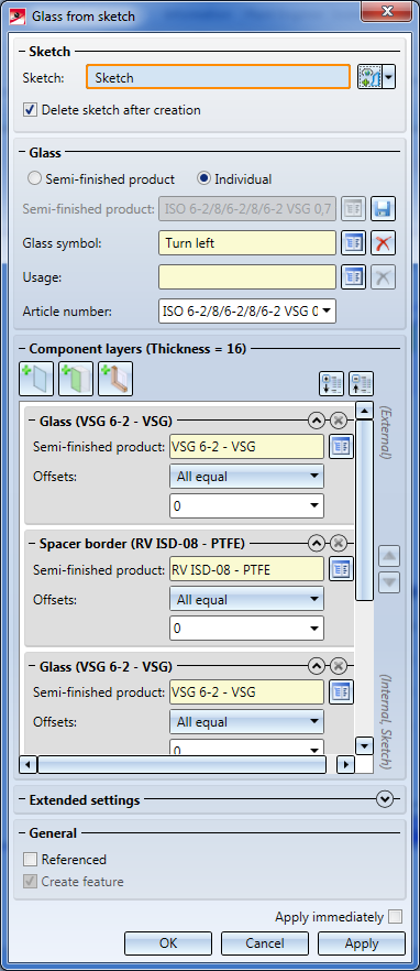
Here you can use one of the configurations supplied by the ISD or define your own configuration.
In this area of the window you can select the sketch that you want to use for the creation of the glass pane. When you activate the Delete sketch after creation checkbox, the sketch will be disappear immediately after creation of the glass pane. The drop-down menu contains the functions Process sketch, which allows you to process an already existing sketch, and the New sketch in plane function, which creates a new sketch for glass pane creation.
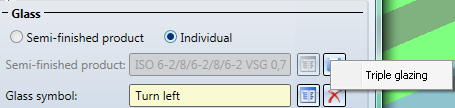
Here you can define some general settings for glass pane creation. First you can choose whether you want to configure the created glass pane according to a Semi-finished product or Individual. If you choose the settings Semi-finished product here, the same-named selection field will be activated, where you can click on the  button and select a semi-finished product from the catalogue. Otherwise this field will be greyed out. You can save the current settings as a semi-finished product to the catalogue by clicking on the
  symbol.
In the selection fields below you can select the Glass symbol and the Usage for the glass pane to be created. Use the buttons to choose a glass symbol/a usage from the catalogue or to delete  your selection again if you do not want to a glass symbol/ a usage.
In the Article number field you can enter an article number of your choice. If you use a semi-finished product, this filed will be filled in automatically, but can still be edited.
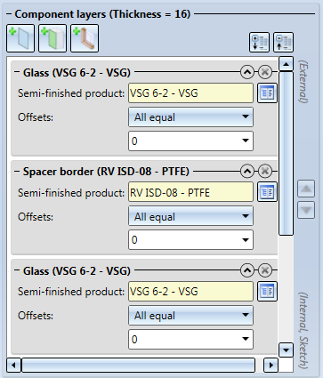
In this area you determine of which layers the glass pane is to be composed. If Semi-finished product has been selected, you cannot specify any settings in this area. Otherwise, you can configure the layers of the glass pane here.
You can add further layers via the  Add layer with glass,
  Add interlayer and
  Add layer with distance frame buttons. The chosen layers will be added at the end of the list. You can also move the layers by marking them with a mouse click and then clicking on the
 icons to move the layers up or down in the dialogue. The uppermost layer in the list will lie directly on the sketch and the following layers below it.
The entries for the layers in the list can be expanded or collapsed with the arrow symbols 
 at the top right. In expanded state the settings for this layer are visible; the collapsed state saves space and provides a clearer overview of the layers. Click the
  button to delete a layer.
In the settings for a layer you can choose a Semi-finished product from the catalogue. Depending on the layer type, selection options may be very limited: If you click on the Add interlayer button you can, of course, only select interlayers. Furthermore, you have the option to define Offsets, i.e. a distance to the XY-plane of the sketch. You can choose between the options None, All equal on all borders of the layer, and Individual for different offsets for the borders of the layer. Positive offset create an offset "into" the sketch, i.e. the layer will be smaller than the sketch; negative values create an offset beyond the sketch borders, i.e. the layer will be larger than the sketch.
In the Individual mode, the borders of the sketch will be numbered. When one of the input fields has been selected, the corresponding border of the sketch will be highlighted:
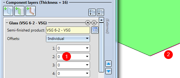
(1) Selected input field; (2) Highlighted sketch border
If you have activated the Chamfers, individual option in the Extended settings, additional input fields will appear for the glass layer entries:
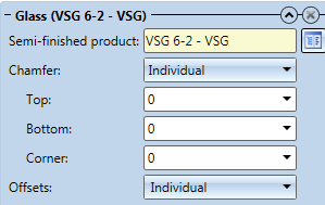
Here, too, you can choose between None, All equal if all chamfers are to have the same length, or Individual if you want to specify the chamfer lengths separately for top side, bottom side and corners.
Click the symbol to expand the Extended settings area:
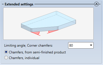
Here you can define via the Limiting angle, corner chamfers from what angle a corner chamfer is to be created for a glass pane. Angles that are smaller than the value specified here, will not be chamfered at their corners.
![]() Please note:
Please note:
After defining an individual configuration for a glass pane you can save it as a semi-finished product to the catalogue and, if required, reuse it later.
To save a glass as a semi-finished product, first make sure that you have entered a correct Article number for this glass pane, since the semi-finished product will be saved to the catalogue with this number.
Then, click on the symbol next to the Semi-finished product input field.
HiCAD will then ask you to choose a table to which the new catalogue entry is to be saved. Please note that one table has always a fixed number of layers, i.e. it is not possible to store one single layer glass with 1 layer and a double glazing with 3 layers in the same table. Therefore, HiCAD will only offer tables with a matching number of layers:
If yo table exists yet for the required number of layers, HiCAD allows you to directly create a new table:
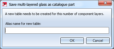
Enter a name for the new table. The table will be created and directly be selected as target table.
If an entry with the same name already exists in the selected table, you cannot save the glass as a semi-finished product here. In such cases HiCAD will display the following message:
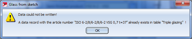
In such cases you need to change the article number and repeat the saving.
The entries will be saved to the catalogue Factory standard > Multi-layered glass panes > Semi-finished products.

Plates (3-D SE) • Steel Engineering Functions
|
© Copyright 1994-2018, ISD Software und Systeme GmbH |