Exchange Parts (PE)
To be able to exchange parts, the following conditions must be fulfilled:
- To be able to exchange a part that is set on a guideline, it must be joined to Connection 1 or 2 directly or with a flange to an arbitrarily divisible straight pipe.
- To be able to exchange a part placed on the corner of a guideline, it must either be directly joined to Connection 1 or 2 or with a flange to an arbitrarily divisible straight pipe.
- If you want to exchange a part that has a third connection, e.g. T-piece, neither a guideline nor another part must be joined to it.
Proceed as follows:
- Select the required type of exchange.
- If required, select the type of insertion.
- Select OK to exit the selection window .The part selected for exchange is deleted. If arbitrarily divisible straight pipes are – directly or with a flange joined to Connections 1 or 2, they are automatically deleted, as well as the flange used for the connection.
HiCAD displays a corresponding result list, if several parts fulfil the search conditions set by pre-settings, e.g. pipe class, and your selection. Select the line containing the appropriate part, and click the Process icon.
- HiCAD expects you to specify an insertion point on the guideline. The replacement part is positioned so that the reference point coincides with the insertion point.
Various options enabling you to specify the reference points are available in a context menu.
- Connection 1 on insertion point
Connecting point 1 is used as the insertion point.
- Connection 2 on insertion point
Connecting point 2 is used as the insertion point.
- Connection1 on origin
Connection 1 is used as the insertion point. The insertion point is the origin of the local coordinate system.
- Show part
HiCAD displays a magnified image of the selected part, thus enabling you to specify a point as the reference point.
Select the required connection function. The part is attached to the cursor by its reference point. Next, specify the insertion point, i.e. the position of the reference point on the guideline or on the guideline corner.
- If the part cannot be symmetrically rotated, HiCAD displays the Rotation angle menu thus enabling you to rotate the part until it is in the required position.
This menu is described in detail for the Rotate part function. When you select End to close the menu, HiCAD inserts the part.
 Please note:
- If the part has flanged connections and the matching flange data is contained in the Anschluss (Connection) attribute, associated flanges are automatically attached to connections 1 and 2. If nominal diameters have been specified for part connections, they are used as search criteria for matching flanges. If a unambiguous result is not found, HiCAD displays a selection list enabling you to select suitable flanges.
- HiCAD automatically closes any remaining gaps in the guideline (or on guidelines that build corners) with straight pipes, i.e. with pipes having the same standard designation as the deleted pipes. If nominal diameters and wall thickness has been defined for part connections, they are used as search criteria for matching pipes. If a unambiguous result is not found, HiCAD displays a selection list enabling you to select suitable pipes.
- In the case of automatically fitted connections, values pre-set for nominal diameter and wall thickness are given higher priority than preset values given for part connections.
- Let us assume that a deleted part is replaced by a reduction with a nominal diameter of 100/50. If a value for the nominal diameter has not been preset, HiCAD attaches a pipe with a nominal diameter of 100 to Connection 1 and a pipe with a nominal diameter of 50 to Connection 2. If a nominal diameter of 100 is preset, then a pipe with a nominal diameter of 100 is attached to both connection.
- The Ignore nominal diameter, AutoFlange and AutoReducer options at the bottom of the dialogue box determine temporary Plant Engineering settings. Original Plant Engineering settings are re-activated when you exit the function.
- You can also replace an elbow, a knee or a corner valve by a T-piece, a 3-way valve or a branch with this function. The procedure is identical to that for the placing of T-pieces, 3-way valves or branches on guideline corner points.
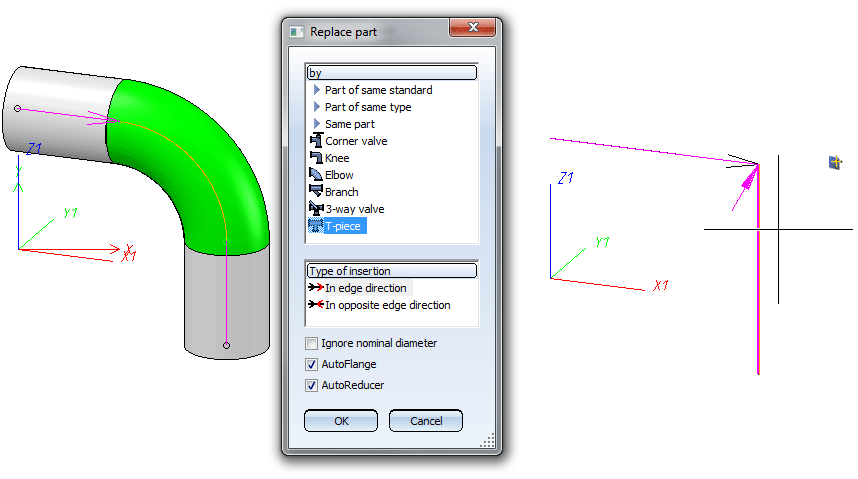
- Select the Exchange parts function, and identify the elbow.
- Select the part type, e.g. T-piece.
- Then. select the guideline for the branch, i.e. the edge on which Connection 3 of the T-piece is to be located.
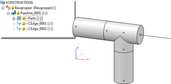
- After this, select - depending on the current Plant Engineering Settings - the T-piece in the HiCAD catalogue or in the HELiOS database. The T-piece will then be inserted. In the process, the guideline will automatically be divided into 2 guidelines at the selected corner. The guideline on which Connections 1 and 2 of the T-piece are now located will be lengthened beyond the T-piece.
Example:

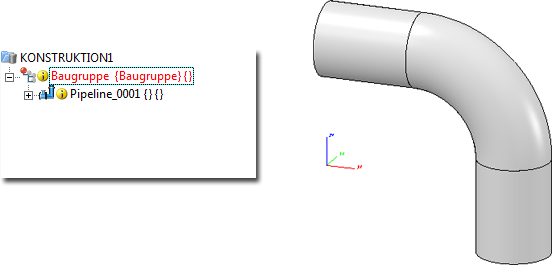
Elbow to be replaced with a T-piece

Selection of pipeline, selection of part type T-piece and identification of guideline for the branching.

Result with T-piece and newly created, lengthened guideline
- If the Use presettings for placing of parts on branching points checkbox on the Part placing on branching points tab of the Plant Engineering Settings dialogue is active, HiCAD will first ask for nominal diameters when you try to place a T-piece, a saddle connection or a straight pipe on a branching point, if these nominal diameters are not already given by the pipeline (or guideline). It will then be checked which definition applies to the current nominal diameter combination. If the part type selected for part insertion does not match the valid definition, a corresponding message will be displayed and the function will be cancelled. e.g.

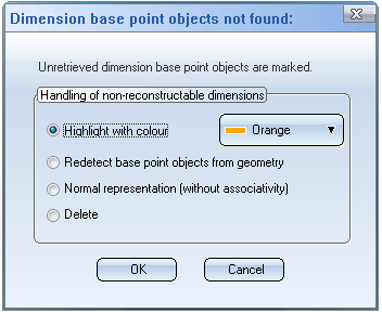
- If parts cannot be updated correctly after part exchange, because dimension base points are ambiguous after transformation or cannot be found any more, the dimensions which cannot be updated are marked and the following dialogue window is displayed:

Then select the option for further processing of the dimensions and exit the window with OK.


Part Exchange (PE) • Part Tools (PE) • Plant Engineering Functions
|
© Copyright 1994-2018, ISD Software und Systeme GmbH
Version 2302 - HiCAD Plant Engineering
Date: 11/07/2019
|
> Feedback on this topic
|
 Please note:
 Please note:


