Create New Cut-Out (3-D)
Views > Edit > Create new cut-out 
 This function will always be applied to the active view. Please select the desired view before you call the function.
To create a new cut-out, proceed as follows:
- Specify the Sketch for cut-out path. Please note that this sketch must be closed.
- If you want to apply an existing sketch, click
 , and identify the sketch in the drawing.
- If you want a
new sketch to be created, click
 , and use the sketch functions to draw the sketch.
- If you want the
sketch to be deleted after you have created the cut-out, activate the
Delete after creation checkbox.
- Define the depth
of the cut-out by specifying a point for the cut-out floor. To do this, click
 , and specify the point you want.
- Use the Preview
button to check the cut-out.
- You can change
the direction of the cut-out by activating/deactivating the Reverse direction
checkbox.
- If you want the
section surfaces to be hatched, activate the With hatching checkbox and then choose the hatching data.
- Click Createif you want the cut-out to be generated with
the current settings.

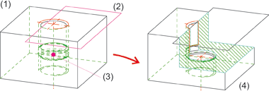
(1) active view, (2) sketch, (3) cut-out floor, (4)
cut-out
 If the sketch lies in the screen plane, the cut-out is directed from
the specified point to the viewer; if not, it is directed from the point
to the sketch plane. If the point lies in the sketch plane, the cut-out
is created in Z-direction of the sketch.
Please also read the notes on the purposes and representation of sketches. Sketches with the purpose Part will be cut in cut-outs, sketches with the purpose Create/Edit will not be cut.
 Important notes on cut-outs
- The active view must
not be an opened sectional view or a surface sectional view. Only standard
views or "standard" sectional views are permitted.
- The active view can
have several cut-outs.
- The settings of the Hatch section view + cut-out function (RMB > Properties ...) may be used when displaying
the section surfaces.
- You can specify the representation of edges in cut-outs in the Configuration Editor, at Drawing > Views >Representation of special lines. There you can select a colour, a line type and a layer for the edges:

- Whether a part is to be considered in a cut-out depends on its section
behaviour, which can be specified with the Cut in sectional view + cut-out function.
- After transformation of a 3-D model, the cut-outs can be adjusted automatically. To do this, select Drawing > Extras > Tools, then choose one of the following options:
- Recalculate cut-outs, sectional and detail views (only active view)
- Recalculate cut-outs, sectional and detail views (all views)
- If a sketch that has been parameterised with HCM constraints contains variables, these will automatically be defined as variables of the view. When using the sketch in a detail view, a sectional view or a cut-out. If you then change the value of the view variables, all views of the current drawing will be updated and the corresponding detail views, sectional views and cuts-outs will be adjusted accordingly. The original sketch, however, remains unchanged. This means that you can adjust view fast and easily without having to change the corresponding sketch.
- Cut-outs that are not up to date are indicated in the ICN by strikethrough view names and by a red cross in the drawing. For example, this is the case if you are working with sectional or detail views and transform the model after definition of the cut-out, or if you apply Boolean operations to the model.
If you do not want the crossed-out representation in the drawing, you can change this in the Configuration Editor at System settings > Visualisation > Views, where you can deactivate the Cross out old cut outs, sectional views and detail views in graphic checkbox.
- To update cut outs, choose Views > Edit > Update
 .
.


View Functions (3-D) • Special Views
(3-D) • Hatching in Sectional View and Cut-Out (3-D)
|
© Copyright 1994-2018, ISD Software und Systeme GmbH
Version 2302 - HiCAD 3-D
Date: 30/10/2018
|
> Feedback on this topic
|


 This function will always be applied to the active view. Please select the desired view before you call the function.
![]() If the sketch lies in the screen plane, the cut-out is directed from
the specified point to the viewer; if not, it is directed from the point
to the sketch plane. If the point lies in the sketch plane, the cut-out
is created in Z-direction of the sketch.
If the sketch lies in the screen plane, the cut-out is directed from
the specified point to the viewer; if not, it is directed from the point
to the sketch plane. If the point lies in the sketch plane, the cut-out
is created in Z-direction of the sketch.  Important notes on cut-outs
 .
. 