

Plant Engineering > Link to P+ID > Show P+ID symbol
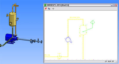
If the assigned P+ID is not loaded, HiCAD automatically loads it as described in the relevant chapter. In addition, you can tell HiCAD to show the P+ID symbol for parts or pipelines on the appropriate sheet of the schema. The associated symbol is colour marked.
The following functions are available:
|
|
|
|
|
|
|
|
 When switching to P+ID, the Object mode is activated automatically. Element and Group mode will be unavailable.
![]()
Plant Engineering > Link to P+ID > Show P+ID symbol for part 
Select the required part. HiCAD automatically switches to the assigned P+ID window where the symbol for the selected part is colour marked.

In the selection window you can enlarge details by drawing rectangles. You can also use the mouse wheel to enlarge or downsize the detail.
The menu bar of the window provides the following functions:
|
|
Close window |
|
|
Selection of another sheet |
|
|
View all |
![]()
Plant Engineering > Link to P+ID > Show P+ID symbols for all parts 
Select this option to show P+ID symbols for all parts.
HiCAD automatically switches to the assigned P+ID window, where all symbols for parts existing in the layout plan are colour marked.You can then use this option in the same way as the Show P+ID symbol for part option.
![]()
Plant Engineering > Link to P+ID > Show P+ID symbol for pipeline 
Select the required pipeline in the layout plan and confirm your selection. HiCAD automatically switches to the assigned P+ID window. The associated pipeline is colour marked.
You can then use this option in the same way as the Show P+ID symbol for part option.
Related Topics
Assigned P+ID (PE) • Plant Engineering Functions • Flow Charts (P+ID)
Version 1702 - HiCAD Plant Engineering | Date: 9/2012 | © Copyright 2012, ISD Software und Systeme GmbH