Profile Installation - What's New?

Service Pack 2 2024 (V 2902)
New attributes for sandwich panels
When installing sandwich panels from the catalogue, you can now access new system attributes. The system attributes are assigned to the contents of the corresponding columns in the catalogue.You can find the catalogues for sandwich panels at Factory standards > Series > Roof Wall Facade > Room-closing profiles,
|
Attribute |
Description |
Catalogue column |
|---|---|---|
|
DWF_T_OUT |
Thickness of outer shell |
THICKNESS_OUTSIDE |
|
DWF_T_IN |
Thickness of inner shell |
THICKNESS_INSIDE |
|
DWF_T_CORE |
Core thickness |
CORE_THICKNESS |
|
DWF_CORE_MAT |
Core material |
CORE_MATERIAL |
Profile images in the packaging list
In addition to the usual bills of materials, packaging lists can also be automatically generated in Excel from a profile relocation. As of HiCAD SP2, these packaging lists show the cross-section of the profiles of the respective package. The designation A and B on the cross-section stands for the positive and negative position respectively. You must create the packages beforehand using the Packaging  function. A packaging list is only generated if at least one package has been defined.
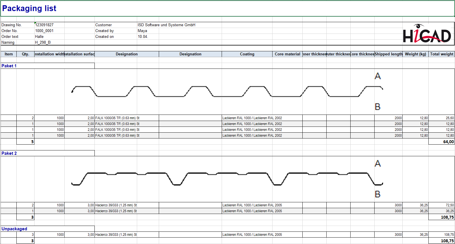
Displayed cross-sections of packaged profiles in Excel
ROMA profiles
As of SP2, panels from the company Romakowski GmbH & Co. KG are now also available for profile installation at Factory standards > Series > Roof Wall Facade > Room-closing profiles > Romakowski.
Service Pack 1 2024 (V 2901)
Licensing
As of HiCAD 2024 SP1, the HiCAD Extension Module Profile installation contains the functions
Additional column in Packaging dialogue
There is now an additional column for a user-specific attribute in the Packaging dialogue. This attribute must be set in the Configuration Editor at Profile installation > Packaging > User-specific attribute.
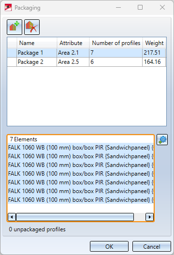
Attribute Comment ($03) set in the Configuration Editor.If you activate the Attribute field for a package by double-clicking on it and then enter a comment, this will be transferred to the part attributes of all parts that belong to the package.
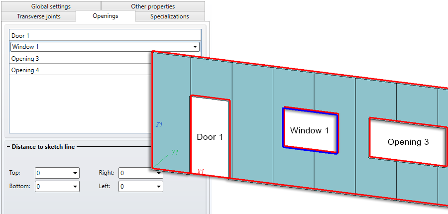
Rename openings
When creating or changing in the Profile installation  dialogue, you can now edit the naming on the Openings tab. By double-clicking in the field of the Opening 1, 2, ... the name can be overwritten. This name is displayed in the preview.
Major Release 2024 (V 2900)
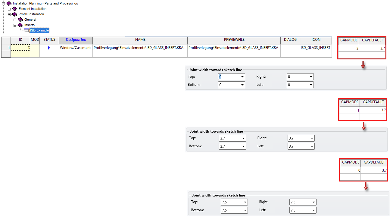
Preset default values for joint width towards sketch line
The joint width towards the sketch line can also be preset in the tables at Factory standards > Installation Planning - Parts and Processings > Profile Installation > Inserts.
To do this, add the table columns GAPMODE and GAPDEFAULT to the tables.
|
Column |
Data type |
|
||||||
|---|---|---|---|---|---|---|---|---|
|
GAPDEFAULT* |
Floating point value |
The desired value for the joint width is entered here. If this value is to be activated as a default, the column GAPMODE must be set to 1. If the corresponding installation element is then selected in HiCAD as insert element of the profile installation, the value for the joint width is automatically set to the value entered in the column GAPDEFAULT. |
||||||
|
GAPMODE* |
Integer |
The value entered here can be 0, 1 or 2.
|
* only for own installation elements and installation elements predefined by the ISD
Example:
Enhancements for Coating
When coating profiles (sandwich profiles), you can now use different colours for the outside and inside. The negative layer no longer affects the coating, i.e. the outer sheet always receives the outer colour. Attributes are set for both coating colours and transferred to the bill of materials.
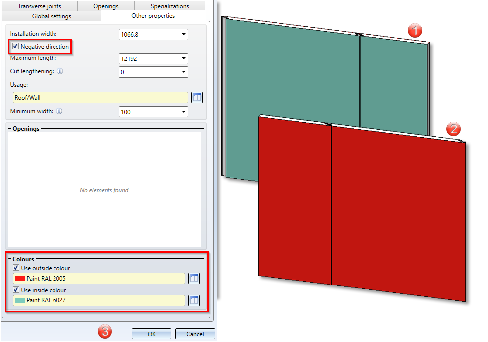
(1) Inside, (2) Outside, (3) Settings in the Other properties tab of the Profile Installation function
Coating of one-piece profiles
One-piece profiles (corrugated and trapezoidal profiles) can now be coated on both sides. If you select only one colour, the profile is also coloured in the graphic. If it is coated on both sides, only the attributes are set and transferred to the BOM.
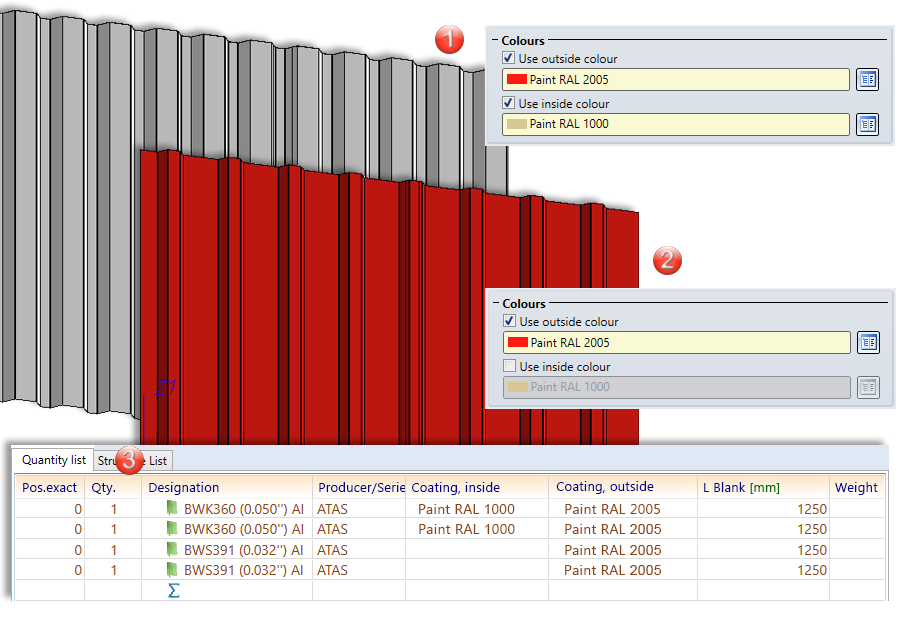
(1) One-piece profile coated on both sides,
(2) One-piece profile coated on one side,
(3) Coating in the BOM
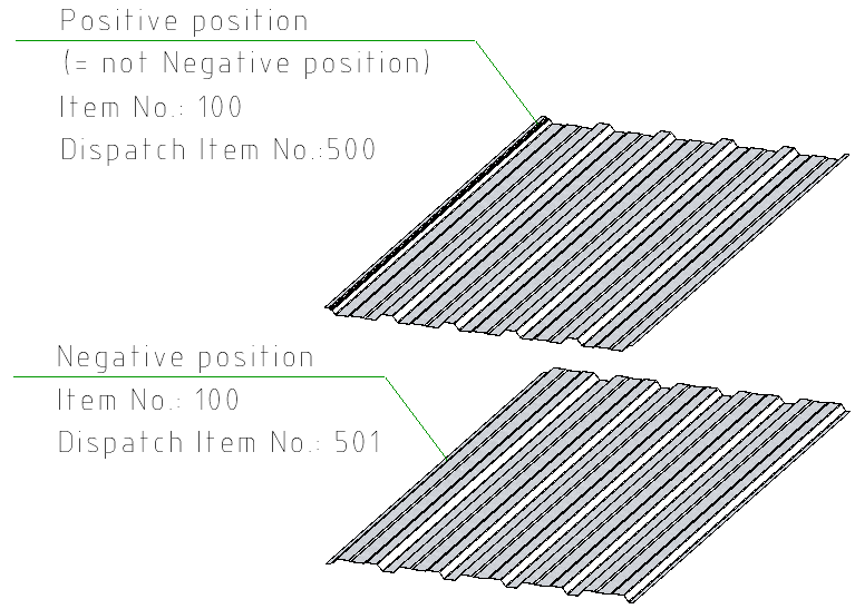
Negative and positive position and identical part search
The negative and positive position of the profiles is a differentiation criterion for the same-part detection during dispatch itemisation. If the value of the attribute DWF_NEG_INSTALL is set to 0, the profile is in a positive position and if it is set to 1, it is in a negative position. In configuration management, it is entered as a distinguishing criterion for dispatch itemisation under Profile Installation > Dispatch itemisation > Integer attributes and is evaluated if the setting Carry out dispatch itemisation is also activated here.
The attribute is not applied to profile installations prior to HiCAD 2024, not even when recalculating the feature.