Other Pipe Parts

Types of insertion
When inserting other parts or placeholders, and when exchanging parts, different types of insertion are available - depending on the selected part.
|
|
In flow direction Here the local coordinate system is set with its origin at the beginning of the leading edge to be selected; the Z-axis lies in the direction of the leading edge. The part is transformed during insertion so that its part coordinate system is aligned with the local coordinate system. By selecting the reference point, the part can be moved along the Z-axis until the reference point coincides with the insertion point. After selecting the part to be inserted, the direction can be adjusted. To do this, the Reverse orientation In addition, the part can also be placed directly at the beginning or end of the guideline. To do this, use the options Place at guideline start
|
|
|
Against flow direction Here the local coordinate system is placed with its origin at the end of the guideline to be selected; the Z-axis is aligned opposite to the guideline. The part is transformed during insertion so that its part coordinate system is aligned with the local coordinate system. By selecting the reference point, the part can be moved along the Z-axis until the reference point is aligned with the insertion point. Here, too, the insertion direction can be reversed as described above. |

 option is available in the


|
On edge branching point With this type of installation, the guideline is automatically divided into two guidelines at the selected corner. The guideline, on which Connections 1 and 2 of the part are now located, is extended beyond the part. |

|
On edge intersection point The prerequisite for this type of installation is two intersecting and perpendicular guidelines. For part insertion, the branching point is identified and then one of the two guidelines. This determines the insertion direction.
Left: Branching point (1), Guideline (2); Right: Branching point (1), Guideline (2a) |
|
|
Connect part Hereby, the part is transformed during insertion in such a way that it is connected, with its selected connecting surface, to a connecting surface of a part that lies on the guideline of the active pipeline. |

Using the classification assigned to the selected part type, parts corresponding to the specifications are searched for in the part data source (database or catalogue) and listed in a results list. The scope of the result list depends, among other things, on the effective preselection.
The preselection can be determined by the pipe class of the selected pipeline and/or the content of the preselection mask. You determine which type of preselection is to be effective or whether preselection is to take place at all in the
 Never delete the link sources via the context menu of the result list, as not only the data records but also the important VAA files will be deleted. You can find out how to delete variants in the database in the topic Part Data Synchronisation.
Placing other parts onto an edge in / against flow direction
- Choose the desired part type in the selection window that then appears and the corresponding type of insertion.
- Select the guideline at the beginning or end of which you want to add the part. The local coordinate system will be aligned accordingly.
- Specify search criteria in the list of characteristics and display the list with the result of all parts that fulfil the criteria.
- Select a part from the list.
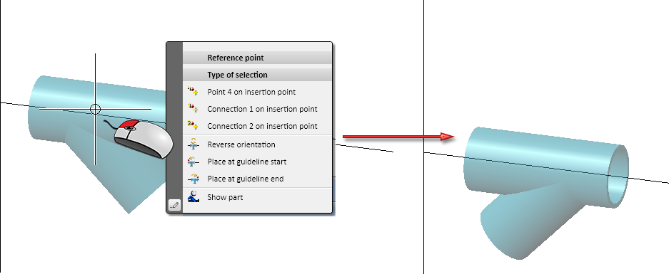
- A message appears stating that the part must not be placed into the guideline, but only onto it. Confirm this message. Select Connection 1 via the reference point menu. The part is now attached to the cursor with this reference point.
- Select the insertion point, i.e. the start or end point of the selected guideline.
- After insertion, the Rotation angle menu appears. Use this to rotate the part to the desired position. The default rotation axis is the selected guideline. If the part is not to be added to the guideline with Connection 1, but with another connection, you can move it to the desired position after completing this function with Move+Rotate part.
- Answer the next query (Same part...) with Cancel.
- If you want to insert the same part a second time, you can now mark the corresponding edge; otherwise finish the process by pressing the middle mouse button.
Inserting other parts into an edge in / against flow direction
- Select the guideline into which you want to insert the part. The local coordinate system will be aligned accordingly.
- Choose the desired part type in the selection window that now appears.
- Select the desired reference point via the Reference point menu: Connection 1 or 2 or a point on the route between both points. The part will be attached to the cursor with the selected reference point.
- Select the insertion point within the selected guideline. Right-click to select the origin of the local coordinate system as the insertion point. The part is inserted at the intended position in the guideline. The edge is automatically divided at the connection points of the part lying on it. The newly created edge hidden by the part is placed on Layer 0.
- After insertion, the Rotation angle menu appears. Use it to rotate the part to the desired position. The default rotation axis is the selected guideline.
- Answer the next query (Same part...) with Yes, if you want to insert the same part again into the originally selected edge. Otherwise, select Cancel.
- You can now immediately select an edge again if you want to insert another part. If not, press the middle mouse button again.
Further notes
- If a pipe class is assigned to the active pipeline, it only becomes effective as pre-selection if you have selected either Via pipeline or Via pipe class + pre-selection mask under Pre-selection on the Part selection tab of the Plant Engineering Settings dialogue window.
- Required reducers are automatically inserted for pipe parts if the following prerequisites are fulfilled:
- The AutoReducer option is activated.
- A nominal diameter is assigned to the active pipeline or a nominal diameter is defined for the guideline on which the part is to be placed.
- The option Ignore nominal diameter is activated.
- A single part (but not a straight pipe) is inserted interactively whose nominal diameter differs from the nominal diameter of the pipeline or the guideline.
The AutoReducer mechanism does not work for the options within the Pipe parts function , which can result in the automatic insertion of several parts, e.g. T-piece, Set all.
- Weld seam gaps can be automatically taken into account when using the Pipe parts functions for pipelines. The resulting gaps between the parts make them immediately recognisable in the layout plan. You determine whether weld gaps are taken into account and the procedure for determining the gap width via the Weld gap tab in the Plant Engineering Settings fest.

Part Selection - Catalogue or Database (PE) • Settings: P+ID Attribute Assignment (PE)