3-D Standard > New > From Skt 
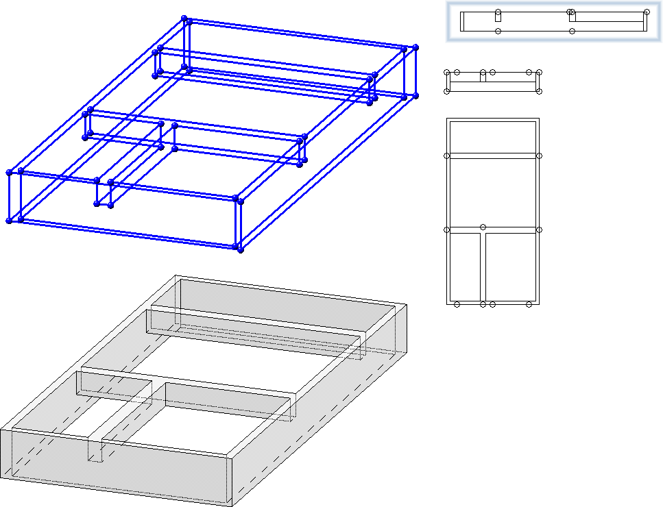
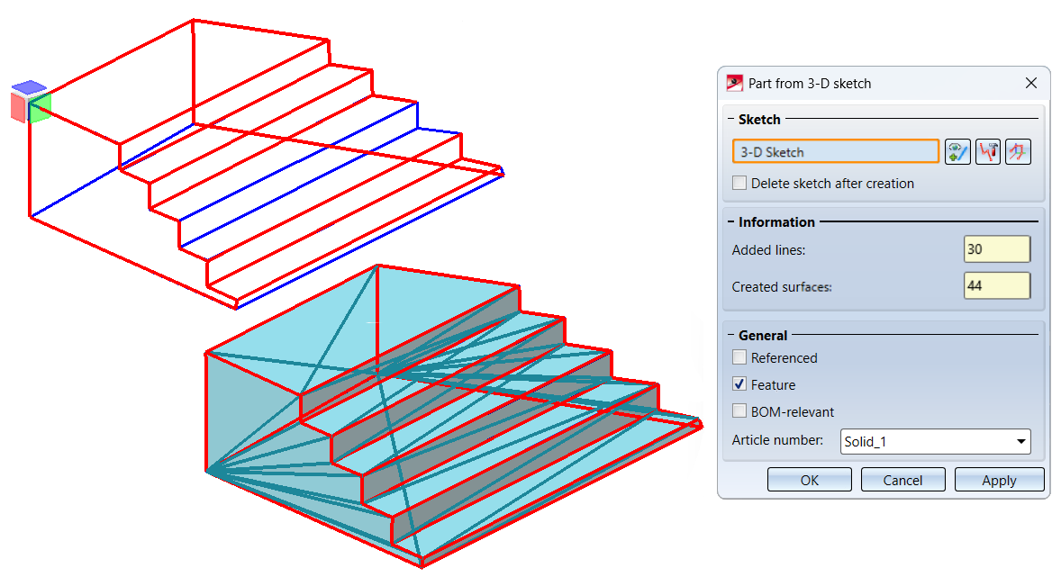
With this function you can derive a solid from a 3-D sketch. This solid consists of planar surfaces and the body edges are the lines of the sketch.
The 3-D sketch must fulfil the following conditions:
- The sketch may only contain straight lines, curves are not allowed. Auxiliary geometry is allowed but will be ignored.
- The lines of the sketch must not intersect or coincide (lie on top of each other).
- The sketch must consist of lines that are supposed to become edges of the solid to be created. Ideally, all edges should be included as lines in the sketch.
- At least two lines must converge at each line end. If this is not the case, the lines are evaluated as errors and visualised accordingly in the graphic. This way, even small gaps in the sketch can be found quickly.
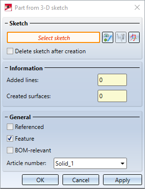
After calling the function, the Part from 3-D Sketch dialogue window is displayed. If no 3-D sketch is active when you call the function, HiCAD prompts you to select a 3-D sketch.
|
|
Select sketch Click on the icon to select another sketch subsequently. |
|
|
Process sketch This function allows you to modify a previously selected sketch. To do this, the Process sketch dialogue window is displayed. Then change the sketch as desired and click Apply sketch in the dialogue window. The dialogue will continue with the modified sketch. |
|
|
New 3-D sketch With this function you can create a new 3-D sketch that will be used to create the solid. Create the desired sketch and then click Apply sketch. The dialogue continues with the new sketch. |


If you want to remove the original sketch from your drawing after the creation of the part, activate the checkbox Delete sketch after creation.
In the General area you can specify the article number of the part and define it by activating/deactivating the corresponding checkboxes,
- whether the part should be referenced,
-
whether a feature should be created for the part and
- whether the part should be BOM-relevant.
If it is possible to create a solid on the basis of the selected 3-D sketch, then a preview of the part is automatically displayed in the design. With a click on the Apply button (or on OK or by pressing the middle mouse button) the part is created.
If the lines of a 3-D sketch are not sufficient for creating a solid, HiCAD will - if possible - insert the missing body edges as a suggestion. You can either accept this suggestion or correct the sketch.
The Information area shows how many surfaces the solid displayed in the preview has and how many lines were added by HiCAD.
If you click Apply, the dialogue window remains open after the part has been created so that you can derive further parts from 3-D sketches without having to call the function again. The dialogue window is closed if you click OK.
If the creation of the 3-D part cannot be carried out, then the  symbol is displayed at the OK button. If the selected sketch does not meet the requirements, the
  symbol appears next to the field for sketch selection. If you point with the cursor to one of the symbols, you will get further information. The corresponding lines and surfaces are visualised in the drawing and highlighted in red. You can then correct the sketch or cancel the function.
Examples:
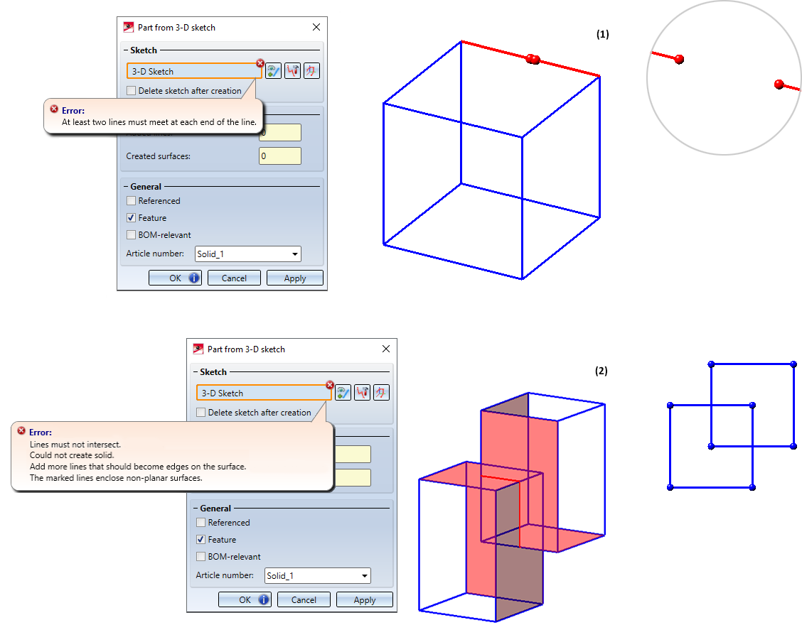
(1) 3-D sketch with gap, (2) 3-D sketch resulting in overlapping surfaces
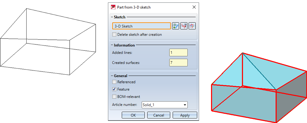
Lines automatically added by HiCAD
In the example displayed, you could also edit the sketch to achieve either this or an alternative result.
If the checkbox Featurewas active when the part was created, a corresponding feature called Solid from 3-D ketch will be created. Double-clicking on this entry opens the Part from 3-D sketch dialogue window, for example to edit the 3-D sketch on which a part is based.
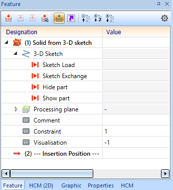
If the 3-D sketch was deleted when the part was created, it can be reinserted into the drawing with Sketch Load.
![]() Please note:
Please note:
- The new part is inserted into the drawing as the main part. If the part should be inserted as a sub-part of the active part or the active assembly, use the function 3-D Standard > New > FromSkt > Sub-part
 .
. - The 3-D sketch can also be parametrised via the Sketch HCM and use variables.
- Planar sketches are not permitted with this function.
- The function is also available in the context menu for 3-D sketches.


Part Creation Functions (3-D) • Notes on Part Creation (3-D) • 3-D Sketches