Notes on Representation
Representation of Beams
Beams can be represented both in simplified form and exactly. The simplified representation does not, for example, display the radii of beams. Furthermore, you can also define whether you want beam annotations, axes and their end points as well as tracing lines of beams to be represented. This allows you, for example, to show and hide beam annotations separately in the workshop drawing and in the 3-D model.
Representation options (from left to right):
exact - simplified - only axes - beam with axes (1) and tracing lines
There are various options for defining the representation type of beams:
- You change the setting in the Configuration Editor at Steel Engineering > Representation > Type of beam representation. This setting will be active when HiCAD is started. The ISD default setting is exact.
- You temporarily change the default setting for the current HiCAD session. To do this, select Steel Engineering > Further functions > Settings
 . In the Representation tab of the dialogue window, define the desired settings, which
will apply to all subsequently created beams.
. In the Representation tab of the dialogue window, define the desired settings, which
will apply to all subsequently created beams. - Right-click the beam and choose the Exact <-> Simplified or Axes+Texts On/Off function in the context menu under Representation. This does not change the standard setting, i.e. you will also need to use the context menu again to show/hide elements that you have shown/hidden via the context menu.
- SelectSteel Engineering > Further functions > Extras
 > Exact <-> Simplified or Auxiliary lines.
 - Select Steel Engineering > Further functions > Settings > Beam/profile axes > Show/Hide, and choose the desired function.
Changing the representation type via feature log
You can also use the feature log to change the representation type – by double-clicking Representation. In the window that is displayed, activate the desired option field and choose OK to exit the window.
Also available here is the Enter formula option, which you can use to assign a variable to the representation type. An example of a typical use case would be, for example, a beam with bores which you do not want to be visible in the simplified representation. Proceed as follows:
- Double-click Representation in the feature log entry for the beam.
- Choose the Enter formula option and enter a variable name, e.g. EXA for exact representation.
- Confirm the value 0.
- Double-click Constraint in the feature entry of the bore.
- Enter the variable name EXA.
The bores are then immediately hidden. If you then choose the Variables of the feature function and assign 1 to the variable EXA, the exact representation is activated – with the bores.
 Please note:
- Switching between different representation types is only used for viewing/checking whether any collisions can occur etc. If you switch between representations while constructing, this can cause problems, especially if external references have been activated in feature technology.
- You can combine several beams into a parts list by using the left mouse button to select the desired beams in the ICN or in the drawing while holding down the CTRL key. Next, you can change the representation of all beams in the part list in one step.
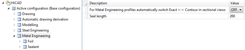
- In the Configuration Editor you can set at Metal Engineering, how series beams with an exact representation and a contour representation are to be displayed in sectional views.
- OFF= as inserted (default)
- ON = always in exact representation).

Representation types for staircases and railings
For staircases and railings created with the Staircase and Railing Configurator the representation type that has been pre-set in the model drawing will be used. The ISD default setting is Simplified.
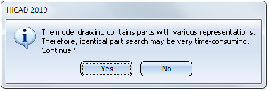
If a drawing contains parts with different representation types, e.g. simplified staircases/railings that were inserted via the Configurators and, at the same time, Steel Engineering objects with exact representation, the representation type will be converted accordingly, on the basis of the identical search, when the drawing is itemized. HiCAD will display the following message:
In some cases, the conversion may fail after clicking Yes:
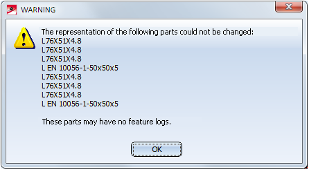
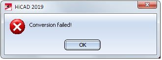
There are two possibilities how to solve this problem:
- Adjust the representation of the Steel Engineering objects to the representation of the staircases/railings.
- Change the representation type for the model drawing via Steel Engineering > Further functions > Settings
 and then update the staircases and railings that were inserted with the Configurators via Steel Engineering > Variants > Update
  . In this case please note that an element of the staircase or the railing needs to be active when you call the function!
Important:
These solution possibilities will only be successful if the staircases/railings are still functional, that is, no parts of the staircase/the railing must have been deleted or broken up. Otherwise, all profiles of the staircase/the railing must be broken up until they appear as individual features in the ICN.e.g..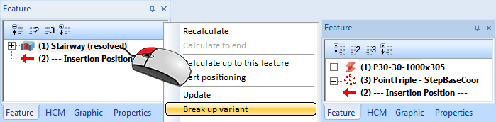

Steel Engineering Settings (3-D SE) • General Information (3-D SE)