Edit Import Settings
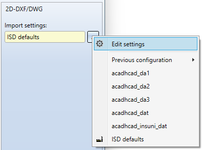
Im import dialogue for 2-D DX/DWG files you can call up an extended dialogue window for the export configuration via Import settings > ... > Edit settings to open an extended dialogue window for the import configuration.
The Import settings 2-D DXF/DWG dialogue window consists of the following tabs:
-
Layers
-
Colours
-
Others
-
Compatibility

General
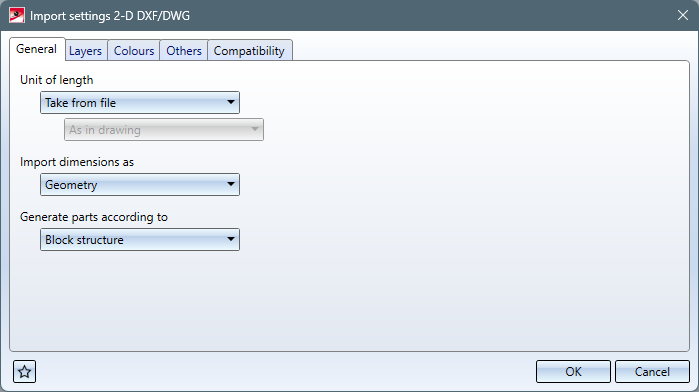
| Unit of length |
For the import, you can select the Unit of length in which the data of the DXF file are to be interpreted. Usually the header variable $INSUNITS of the DXF file is evaluated via the setting Take from file, the data is interpreted according to this header variable and converted into the current HiCAD drawing unit.
Also, you can select Given e in order to select another unit of length in which the data are to be interpreted in the then active pull-down menu below.
In addition to the Millimetres, Centimetres, Decimetres, Metres, Inches and Feet that can be set as import units, you can activate the As in drawing option. However, the HiCAD drawing unit does not change when importing a DXF file depending on the unit of the DXF file. It remains the same, or corresponds to the unit for a new HiCAD drawing when a new drawing is created. |
| Import dimensions as |
Here you can select whether the dimensions of the DXF file are to be generated as 2-D Dimensions or as Geometry. However, real dimensions are generated only if the DXF file already contains dimension objects (DIMENSION). By default, no real dimensions are created, which is why the default setting is Geometry.
If the header variable $INSUNITS of the DXF file is to be interpreted (settingUnit of length = Take from file) and the header variable $INSUNITS of the DXF file contains a unit other than mm, the generation of "real" dimensions may be faulty. |
| Generate parts according to |
This option allows you to select in which structure the geometries and texts of the DXF file are transferred to HiCAD: Block structure or Layer structure. By default, the parts are transferred to HiCAD using the DXF Block structure. If Layer structure is set, a separate 2-D part is created for each layer from the "LAYER" table of the DXF file, to which all geometries and texts of the DXF file with corresponding layer are transferred. (This option replaces as of HiCAD 2023 Service Pack 1 the former keyword setting option "LAYFI" in the corresponding configuration file). |
 In earlier HiCAD versions the $INSUNITS variable was not evaluated and the data was not scaled accordingly. If the $INSUNITS variable is set in the DXF file, the data is now scaled (if it is in a unit other than mm).
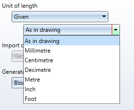
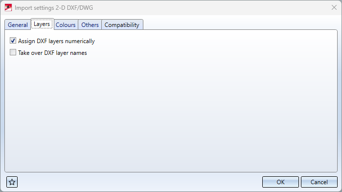
Layers
In the Layers tab of the import settings dialogue you will find options for processing the DXF layers:
|
Assign DXF layers numerically |
This option, activated by default, can be used to control whether DXF layers with a numerical layer name are transferred to the HiCAD layer with the corresponding number. This does not apply to DXF layers with names "0". |
|
Take over DX layer names |
By default, the layer names of DFX files are not transferred as HiCAD layer names. If this option is activated, then the layer names of DXF layers are transferred as HiCAD layer names during import. This setting should only be used if the layer names are also required in HiCAD. |
(These options replace the former code settings "LAYNR" and "LAYNA" in the corresponding configuration file as of HiCAD 2023 Service Pack 1).
Colours
The colour table DXF colour index -> HiCAD colour can be used to assign DXF colour indices to corresponding HiCAD colours.
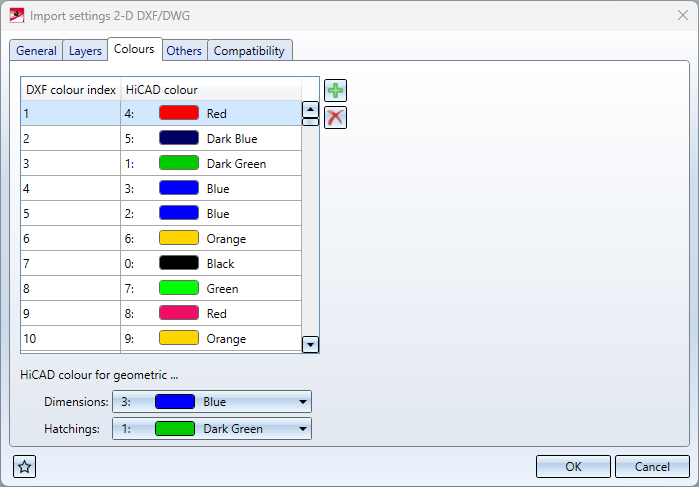
Non-defined colours are assigned the system colour 0 in HiCAD.
In the dialogue window, new rows can be added by clicking on  , or rows can be deleted by selecting them and clicking on
  .
.
Under HiCAD colour for geometric... you can also set the following:
-
Dimensions: Here you can select the colour in which dimensions are created during import. The choice of colour for dimensions is limited to geometric dimensions. By default, geometric dimensions are created in HiCAD system colour 3 (blue).
-
Hatchings: This option allows you to select the colour in which hatchings are created during import. The choice of colour for hatching is limited to geometric hatching. By default, geometric hatchings are created in HiCAD system colour 1 (dark green).
This option only affects "block" hatchings, not "HATCH" hatchings
(As of HiCAD 2023 Service Pack 1, these options replace the former setting options "COLOR" and "COLBE" in the corresponding configuration file).
Sonstiges
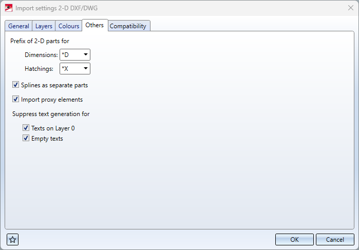
| Prefix of 2-D parts for |
These menu items can be used to define prefixes, which serve as block identifiers for Dimensions and Hatchings. By default, the Dimension prefix is "*D" and the Hatchings prefix is "*X". (These options replace the previous code setting options "BLKBE" and "BLKSR" as of HiCAD 2023 Service Pack 1). |
| Splines as separate parts |
This option can be used to determine whether splines should be transferred to separate 2-D parts. By default, splines are transferred to separate 2-D parts. (This option replaces the former code setting option "SPFIG"). |
| Import proxy elements |
This option can be used to determine whether PROXY elements of the DXF file should be transferred. DXF/DWG files can contain PROXY elements, in which a large part of the geometry can be located. These elements are generated by AutoCAD add-on programs and can only be represented exactly with them. However, a proxy graphic is usually entered in the DWG/DXF file. With this option these proxy graphics can be transferred to HiCAD. By default, the option is active. (This option replaces the former code setting option "PROXY"). |
|
Suppress text generation for |
Texts on Layer 0: With this option it can be suppressed that texts are generated which are on DXF Layer 0. By default, texts on Layer 0 are not transmitted. (This option replaces the former code setting option "TSCH0").
Empty texts With this option the generation of empty texts can be suppressed. By default, empty texts are not generated. (This option replaces the previous code setting "TLEER "). |
Compatibility
On the Compatibility tab you will see a list of all set configuration Codes, their respective Values and a Comment line.
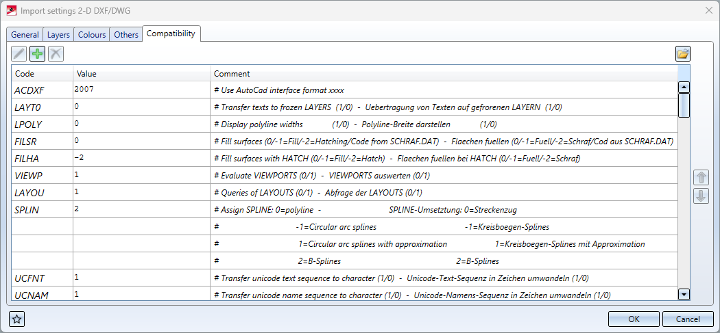
You have the option here to change the settings based on system files. The settings include the assignments of colours, line styles and fonts.
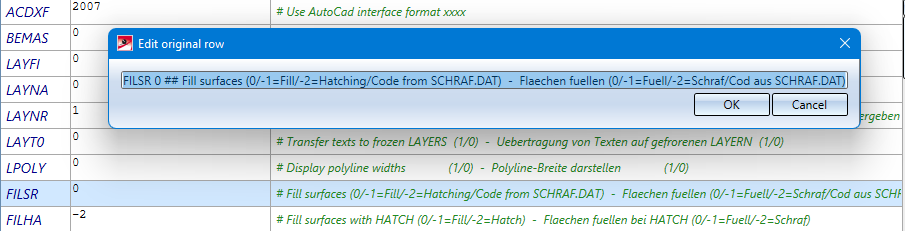
You can change a Value by clicking in the corresponding field and changing it manually.
You can edit an entire row including Code and Comment by selecting it and clicking on the pen symbol on the right.
You can load the configurations from older configuration files (ACADHCAD.DAT) by clicking on the  at the bottom of the window and selecting a corresponding one in the following selection dialogue.
Clicking on the  at the bottom left of the dialogue opens the Favourites menu.
Below you will find explanations of some codes:
With DXF splines (B-splines) the node vector can also be transmitted. This achieves a very good correspondence with the ACAD course. The SPLINE value must be set to 2 for this.
SPLINE: B-splines with node data cannot be generated interactively in HiCAD. Similarly, node points entered via DXF cannot be changed interactively. Therefore, when changing the number of spline control points, the error message Error in B-Splines: node and control point data do not match; the node data can then be deleted.
Surfaces filled in the DXF definition (SOLID and POLYLINE) are filled in HiCAD with a part hatching if an entry FILESR [number of the HiCAD hatching code] can be found. The filling only takes place if a number greater than 0 is entered here and the switch $FILEMOD is set to 1 in the DXF file itself. Hatching exclusions are entered as drawing parts, i.e. as secondary parts which do not appear in the part list.
Via LTYPE you can determine the assignment of DXF-LINETYPES to HiCAD-line types. Blank spaces are represented by dots. Via the entry * all LINETYPES not explicitly agreed upon are assigned to the specified HiCAD line type. As a second number, a line colour can be assigned (-1=ignore). Likewise, a colour can be assigned to an entered line type via COLAR. COLAR has priority over any colour assignments via COLOR or LTYPE.
With the entry LAYT0 you can prevent the transfer of texts on frozen layers which are placed on layer 0 without this entry.
The following applies to the LAYOU setting :
LAYOU 0: Read all layouts at once (incl. model) without query
LAYOU 1: Offer the layouts and the model, as well as the option 'all' (when selecting individual layouts, the model is now always deleted)
("< 0": identical with 0; " > 1": identical with 1)
In the case of list processing, everything is read in independently of .DAT.
The CodePage No. to be used as default can be entered via CPAGE. The CPAGE entry is then evaluated as follows:
- CPAGE = 0 : Do not evaluate the CodePage entry of the DXF file
- CPAGE = 1 : Evaluate CodePage entry of DXF file
- CPAGE > 1 : If CodePage entry DWGCODEPAGE-No.=CPAGE
- Example: "CPAGE 932" = default Japanese CodePage
- Example: "CPAGE 1252" = default German CodePage
The meaning of the entry STYLE is an extension for fonts and automatic determination of the font from the DXF font width: The text font can now be entered as the second code number (after the font) (default =1). If a 0 is entered in the font column, the actual font is automatically determined from the font width and slant angle. For better adaptation, a correction factor for the font width determination can be entered behind the text font column (generally values >= 1); the smaller this factor, the narrower the font found. If -1 is entered in the font column, the font width is determined flexibly (width factor) with font 1. Correction factors can also be used here.
Example: 'STYLE STANDARD 0 2 0.9' >= Textfont=2, automatic determination of the font (width value reduced by 0.9)
It is recommended to carry out a test with both font 1 and font 2 to determine optimal results, as different results occur between linear and proportional fonts.
DXF/DWG material hatchings (HATCH) are always transferred as 2-D part hatchings. The HiCAD symbol hatching 3309 (from sys\Symbtab.SZA) can be assigned to the DXF hatching "SAND" via the identifier SYMSR, e.g. "SYMSR SAND 3309 0.5", and the symbol distance is multiplied by 0.5 as a factor. The DXF hatching name can be taken from the rear portion of the part name of the hatching in HiCAD (here: "_HATCH__SAND").
The keyword ASCII can be used to convert special characters, e.g. ASCII 204 132. All characters of the number 204 of the source DXF are converted into characters of the number 132. This command is especially applicable for converting umlauts of other operating systems to the currently used operating system. HiCAD uses the ANSI character set.
![]() Please note:
Please note:
Designations (e.g. font names) that contain spaces must be placed in double inverted commas. E.g.: STYLE T4 ''Times New Roman'' times.ttf 1.0
Please also observe the following notes on 2-D DXF/DWG import:
- Importing DXF - Evaluating the line-weights
A weight-colour assignment can be made. No. 0 defines the colour of the STANDARD assignment; 9 numbered lines follow for the weights:
COLWE 0 0 # STANDARD
COLWE 1 7 # 0.13 # COLWE Consecutive No. colour
COLWE 2 7 # 0.18
With colour = -1 the algorithm is generally switched off (COLWE 0 -1))
The line type ranges 1-9 are defined according to DIN. The weight entry in the DXF has priority over a colour entry, regardless of the order of the groups in the DXF file.
- Importing DWG/DXF - Read all layouts at once into HiCAD sheet areas
For the setting LAYOU applies::
= 0: Read in all layouts at once (incl. model) without query
= 1: Offer the layouts and the model, plus the option All (when selecting individual layouts, the model is now always deleted)
< 0: identical with 0
> 1: identical with 1
Regardless of the setting, everything is read in during list processing. When creating DXF files, only the currently visible image is transferred as before, i.e. only the active sheet area.
- Importing DXF with SPATIAL-FILTER
For this purpose the entry SPAFI 1 or 0 (1=default) has been added.
This entry evaluates the area filter (DXF = SPATIAL-FILTER) possibly assigned to the DXF-parts (blocks).
Without the filter (SPAFI 0) it can happen that elements are transferred in HiCAD which are not visible in the source file - with filter these elements are deleted.
