Process Blank
Sheet Metal > Sheet development > Update  > Up to HiCAD 2016 > ...
The Up to HiCAD 2016 sub-menu (Sheet development > Update >...) contains functions for the processing of 2-D developments that could be created with HiCAD up to Version 2016. From HiCAD 2017 onwards, only 3-D developments can be created.
|
Functions |
Description |
|
|---|---|---|
|
|
Use this function to change the blank parameters of a selected blank. |
|

|
Use this function to change the blank parameters of all 2-D developments or blanks in the drawing. In the dialogue window, activate the checkboxes for the parameters that are to be shown in the blank. |
|
|
|
You use this function to simplify a development with the aid of the zoom function.
This area is now displayed enlarged.
The corner is simplified. You can now process more developments or use the middle mouse button to end the function.
(1) Zoom rectangle |
|
|
|
Corners and relief grooves which are smaller than the entered circle are deleted from the blank. Specify the radius for the circle and then identify the blank (development).
(1) Circle via radius specification |
|
|
|
Use this function to change the scale of a development. You can assign a different scale to each development in the drawing. Proceed as follows:
|
|
|
|
The development will now be dimensioned. If you want to remove the dimensions, activate the 2-D Dimensions + Text tab and select Process > Extras > Part > Delete dimensioning. |
|
|
|
This function enables you to delete the link between sheet construction and 2-D blank. If you adjust the sheets afterwards, the previous blank will be preserved and will not be updated. |
|


![]() Please note:
Please note:
- If you are working with referenced parts, please remember the following:
The link between 3-D part and 2-D blank is made, once the edge to be developed has been selected, by means of two points placed in layer 0 which lie on the edge and on the corresponding lines in the blank. If these points do not exist, the blank will be re-generated, rather than updated.
When using referenced parts, you therefore need to bear in mind that an update can only be performed if the referenced part is saved after the blank is generated and no new development of the part specifying another edge is generated after this. - To be able to place the 2-D blank in a separate view, open the Configuration Editor, go to Compatibility > Sheet development up to HiCAD 2016 > Visibility of 2-D blank and choose the option Active drawing sheet.
- You can display the angle or the height of cross-breaks in blanks. To do this, open the Configuration Editor, go to Compatibility > Sheet development up to HiCAD 2016 > Annotation for cross-break and choose the desired option.
- To enter the sheet thickness into the part attributes, the part attribute Height was used in older versions. Now, a separate attribute for the sheet thickness is available for this purpose. If you prefer to enter the thickness via the Height, please enter the following parameter in the Configuration Editor as follows:
Compatibility > Sheet development up to HiCAD 2016 > Dimensions from development edge (§L2D,§B2D,§T2D, 1 + §02,§03,§04, 1 + §04) 1 + §02,§03,§04
The calculation of the surface area for Sheet Metal parts for the part attributes takes place in square millimetres. For the transfer to the BOM, these values are converted into square metres.
For sheet processing, a special BOM configuration called HICAD_Blech*.RMS is available.
The system attributes
|
§L2D |
Development length |
|
§B2D |
Development width |
|
§T2D |
Sheet thickness |
will be considered for the part attribute transfer to the Report Manager. This does not apply to database BOMs, though.
- The changes in the Configuration Editor will, be applied after a restart of HiCAD.
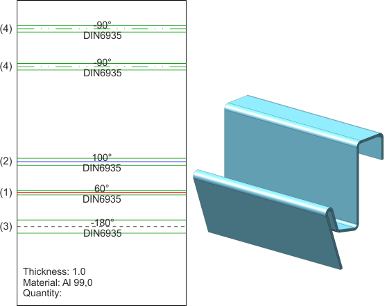
- You have the option to individually specify bend lines in blanks. To do this, open the Configuration Editor, go to Compatibility > Itemisation control > Extended settings > Set bend line colour depending on bend angle.
Then, change the settings in the file ABWCOL_BEND_ANGLE.DAT. Simply save the file to apply the changes after updating of the blank.
Positive and negative bend angles are distinguished the file ABWCOL_BEND_ANGLE.DAT. Only the data within the BEGIN-END block may be changed.
| Biegewinkel von (Bend angle from) |
Biegewinkel bis (Bend angle to) |
Liniencode(Schicht,Farbe,Staerke,Art) (Line code (Layer, Colour, Weight, Type)) |
|
|
Linienparameter für Biegung nach unten, d.h. negativer Biegewinkel |
|||
|
BEGIN |
|
|
|
|
(1) |
0.0 |
95.0 |
2411 |
|
(2) |
95.0 |
360.0 |
2311 |
|
END |
|
|
|
|
Linienparameter für Biegung nach unten, d.h. negativer Biegewinkel |
|||
|
BEGIN |
|
|
|
|
(3) |
-360.0 |
-95.0 |
2013 |
|
(4) |
-95.0 |
0.0 |
2117 |
|
END |
|
|
|


Overview of Functions • General Information on Sheet Metal Processing • Development • Allowance Method for Developments