Auxiliary drawing parts
HiCAD also manages objects without part character, e.g. 2-D auxiliary lines, DIN frames etc. If you want these objects to be displayed in the part structure proceed as follows:
- In the 2-D tab of the ICN, right-click the drawing name.
- In the context menu, choose Auxiliary Part On/Off and then ON. This setting applies temporarily to the current HiCAD session. To switch off the display of the auxiliary parts again, set the setting to OFF.
To change the setting permanently, open the Configuration Editor, select System settings > Miscellaneous and activate the Auxiliary parts in browser checkbox.
The "2-D Parts" part
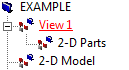
When you create a new drawing, a main part with the name View 1 is always inserted into the 2-D structure. A sub-part with the name 2-D Parts is assigned to this main part. Whenever you choose a new 3-D view, the name of the main part is adjusted to the selected view in the 2-D structure, e.g. ENG.AXONOMETRY 2 or TOP VIEW. This part has a purely organisational purpose and cannot be deleted! If you insert 2-D geometry elements into a 3-D view without defining a new 2-D main part beforehand, they are automatically assigned to the 2-D Partssub-part.
Initial 2-D Structure
Example:
- Let us assume that you create a new drawing. In this case, the first 3-D view is automatically generated. The default setting is "3-D Modelling View 1". A part with the name VIEW 1 and the sub-part 2-D PARTS is therefore entered into the 2-D structure. The 3-D structure is then still empty.
- If you now create a new 3-D main part, e.g. with the name CUBOID, a main part with the name CUBOID is entered into the 3-D structure. The 2-D structure only changes if you activate a new 3-D view. In this case, the name of the part VIEW 1 is replaced by the name of the new view.
 Listed will always be those 2-D view figures that belong to the active sheet or the active model, respectively.
The parts "2-D Model" and "2-D Sheet"
All 2-D parts located beneath the 2-D Model part are visible if a model view is activated. All parts located below 2-D Sheet are visible if a sheet view is activated (e.g. drawing frame).
In contrast to the 2-D parts located beneath an individual view, these parts are even visible while using the Show only active view setting.
How do you use the "2-D Sheet" part in practice?
Let us assume that you want particular 2-D parts such as a BOM, a tolerance table, or a part that you have created yourself (e.g. with processing hints) to be visible only in the views of the Sheet area, but not in the Model area.
For this purpose, activate a view in the Views tab of the ICN. Please note that the display will only be updated after moving of the cursor onto the drawing area. In the 2D-Part structure tab of the ICN, move the BOM, the tolerance table and the processing hints below the part "2-D Sheet". The 2-D parts will then be invisible in the view of the Model area.
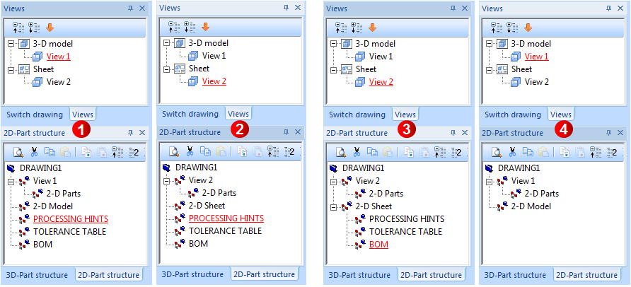
(1) 2-D part structure in the Model view, (2) 2-D part structure in the Sheet view,
(3) 2-D part structure in the Sheet view after moving of the parts PROCESSING HINTS, TOLERANCE TABLE and BOM below the part 2-D Sheet
(4) 2-D part structure in the Model view after moving of the parts


Part Drawing or Assembly Drawing • 2-D and 3-D Model • 3-D CAD