Docking Windows
Docking windows are windows that contain commands and settings for certain tools or tasks. These are "docked" at the edge of the HiCAD screen.
Docking windows can be shown/hidden by selecting Settings > Docking windows:
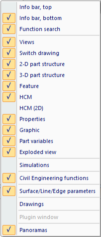
HiCAD supports docking windows as follows:
|
ICN Docking window |
Contents / Purpose |
Position on screen |
|---|---|---|
|
View structure of the current model drawing |
Left |
|
|
Currently opened model drawings |
Left |
|
|
Part structure of the current model drawing |
Left |
|
|
Feature log of the active 3-D part |
Left |
|
|
HCM constraints of the active part |
Left |
|
|
Attribute of the active part |
Left |
|
| Graphic preview of the active part |
Left |
|
| Part variables |
Displays the part variables of the active part |
Left |
|
Further Docking windows |
Contents / Purpose |
Position on screen |
|
Shows a log of an exploded view of a model drawing |
Right |
|
|
Tool allowing simulations of movements of parts |
Right |
|
|
Insertion of joints and connections, fasteners, stairs and railings or other objects |
Right |
|
|
Faster opening of HiCAD drawings (.SZA) |
Right |
|
|
Assigning of panoramas for environment simulation |
Right |
|
|
Integration of freely definable plugins |
Right |
|
|
Texts for user guidance |
Top / Bottom |
|
| Pre-settings for the display of surfaces, lines and edges |
Bottom |
|
|
Helps to find a specific function |
- |
The following options are available for the processing of the windows:
- Change window size
You can change the size of the individual drawing windows by dragging the window frames to the required size (press and hold down LMB and drag).
- Show/Hide tabs
The windows as well as individual tabs of the ICN can be hidden and redisplayed. For this you use the  Settings > Docking window function.
- Functions of the context menu
A context menu provides further processing options for the windows. You activate the context menu by right-clicking on the required window.
- Floating
Use this function to change the fixed position of a window. The window is downsized and can then be moved freely. - Docking
Use this function to re-dock floating windows. - AutoHide
This function enables you to dynamically hide and show windows. If you apply the function to a displayed window, the window will be hidden and redisplayed as a tab on the right hand side of the HiCAD window. If you place the mouse pointer on the tab entry, the window is shown. If you move the mouse pointer out of the window, it is hidden again. Alternatively, you can also use the symbol at the top right of the window. The symbol changes its appearance to
  .
.
- Hide
Use this function to hide windows. This corresponds to the deactivation of the window with the Settings > Docking window function.
- Move window
Undocked windows can be freely moved with the mouse. Place the cursor on the caption bar of the window, press and hold down the LMB, drag the window to the required position and drop it by releasing the LMB.
- If you want to align the window to one of the borders of the HiCAD screen, use one of the automatically displayed arrow symbols shown below:

- If you want to align the window to another docking window, move the window in the vicinity of the required other docking window, and click the appropriate arrow symbol.

In addition, you can define the window as a tab of the docking window: Use the  symbol for this. If you want to revoke this assignment as tab, left-click on the corresponding tab and, while holding down the LMB, drag it to the required position.
Zooming contents
The contents of various docking windows can be enlarged or downsized dynamically by zooming. This is possible for the following docking windows:
- Views,
- 2-D/3-D Part structure,
- Feature,
- HCM (2-D) und HCM (3-D),
- Part variables,
- Exploded view.
|
|
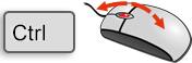
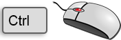
Zoom contents of one docking window To enlarge or downsize the contents of a single docking window, point the mouse cursor inside the window and turn the mouse wheel while holding down the CTRL key. |
|
|
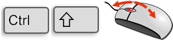
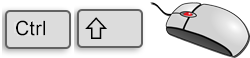
Zoom contents of all docking windows To enlarge or downsize the contents of all docking windows, turn the mouse wheel while holding down the CTRL and the SHIFT key. |
|
|
Reset zoom The zoom of the active window can be reset by pressing the CTRL and middle mouse button simultaneously. To reset the zoom of all windows, press CTRL, SHIFT and the middle mouse button accordingly. |

Docking window: Drawings
The Drawings docking window enables a quicker opening of HiCAD drawings. (.SZA). Simply select the required folder and double-click on the required file name.
If the window is not displayed, activate it via Settings > Docking windows.
This docking window can also be switched off permanently via the Window Registry. To do this, create in the Windows Registry at
HKEY_LOCAL_MACHINE\SOFTWARE\ISD Software und Systeme\HiCAD\3
a new DWORD value (32) Bit and assign the value 1 to it.

The docking window can then no longer be activated in HiCAD. If you want to re-enable the activation of the window, set the value in the Registry to 0.
Docking Window: Civil Engineering functions
Use this docking window to fit joints and connections, fasteners, stairs, railings, or other objects in Steel Engineering or Metal Engineering drawings.
Docking window: Panoramas
HiCAD offers the option to simulate environments. For this purpose a panorama is assigned to a Sheet or Model area. The surfaces of shaded models can then mirror this panorama, i.e. the environment.
This panorama can be used as background as well as for visualisation of environment mirroring.
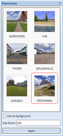
Assign panorama
- In the Panoramas docking window, select the desired panorama.
- Activate the Use as background checkbox if you want to use the panorama as background of the sheet or model area. Please note that the corresponding area must not contain more than one view.
- Specify the Size factor and click Apply.
If the surfaces of shaded models are to mirror a panorama, i.e. the environment, activate the environment mirroring. To do this, use the Shaded view function under Shaded representation via Views > Representation > Shad... In the dialogue window, acitivate the checkbox Mirror panorama. Deactivate the checkbox to undo this effect.
Plugin windows
HiCAD supports the integration of freely definable plugins. If such plugins have been implemented in your system, they will be displayed in a docking window. Examples are the templates for planning grids in Metal Engineering or the Sheet Metal Cost Calculation tool.
Docking window: Simulation
You can use this tool to simulate and animate movements of parts in an assembly. You can also use HCM constraints to link the movements of individual parts to particular conditions. To be able to define or edit simulations, the Simulation docking window needs to be open.
Docking window: Part variables
In this docking window the Part variable of the active part and (if any) also those of the superordinate parts are displayed.
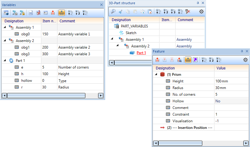
The symbols in front of the Part variables indicate the type of the variable.
Part variables/View variables
With the first symbol  it is possible to switch between Part variables and View variables. If the automatic feature recalculation
  is active, the views will be recalculated.
Activate/Deactivate variables of active feature log
This filter  restricts the display of all variables used in the feature log of the active part.
Activate/Deactivate variables of active HCM model
This filter  restricts the display of all variables used in the active HCM model.
Add variable
To add a new variable, click on the  symbol. You can also click with the right mouse button on the name of the part (or the assembly) which should be attributed to the variable. In the context menu, select the function Add new variable.
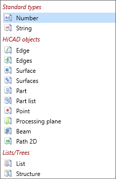
In the next dialogue window, determine the name of the variable, select a variable type and set a start value. If requested, a comment can be added. The following variable types are supported:
After leaving the dialogue window with OK, the new variable will be entered.
Mark unused variables
With a click on the  symbol you can mark all unused variables for deletion. The deletion is not executed until you call the Delete
  function from the context menu
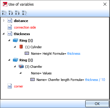
Variable, where-used
With a click on the  symbol you can open the Use of variables dialogue window, which lists for all variables of the selected part where (and whether) they are used elsewhere in the drawing.
Recalculate
Use this symbol  to start the feature recalculation of the active part or the recalculation of all views.
Activate/Deactivate automatic feature recalculation
The automatic feature recalculation or recalculation of all views can be switched on or off via this symbol .
Expand/Collapse structure
The display of the part variables can be completely expanded or collapsed according to the part structure by using the symbols  and
and  at the top of the docking window. Use the
  icon to limit the display to the 1st and 2nd level of the part structure.
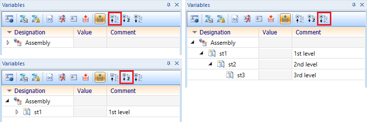
For opening/closing the variable display of each parts/assemblies use the symbols  and
and  .
.
Context menu for parts / assemblies
If you right-click on a part or assembly name, the following functions are available in the context menu, in addition to the functions from the toolbar:
|
Function |
|
|---|---|
|
Delete duplicates in sub-parts |
Duplicates of variables already defined in the superordinate part are marked in this part and deleted depending on the choice of the funtion. |
|
CSV export |
Clicking on the function creates a CSV file containing a list of all variables. |
|
CSV import |
This function imports variables from a CSV file into the selected part. |
|
Copy |
All variables of the part are copied to the clipboard. |
|
Insert |
The variables from the clipboard are imported into the part. |
Context menus for variables as well as structure and list variables
Analogously, context menus for variables can be called by right-clicking. With the functions of these menus you can
|
Function |
|
|---|---|
|
Delete |
Deletes the variable from this part. Multiple selection possible. |
|
Rename |
Starts the dialogue for renaming. |
|
Edit formula |
This function starts the formula editor for number variables. |
|
CSV export |
Here the variable will be exported to a CSV file. Multiple selection possible. |
|
CSV import |
In structure variables you can import CSV files with this function. |
|
Copy |
Here the variable is copied to the clipboard. Multiple selection possible. |
|
Insert |
You paste variables from the clipboard into a structure variable with this function. |
To change the value or comment of a variable, simply click in the corresponding field and enter the desired change. Then apply the change by clicking OK.
Please also read the information in the Value Input (General Advice on Formulas and Variables) topic of the Feature Technology Help.
Exploded view
This docking window shows a log of an exploded view of a model drawing.
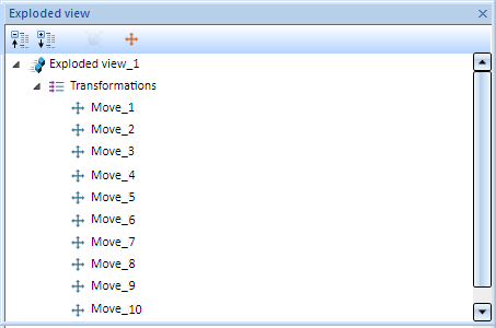
Exploded views can be edited subsequently via this log.
