View Marking According to Arrow Method
Views > Edit > View marking according to arrow method ![]()
If views are derived manually or automatically from other views, then in practice it is sometimes advantageous to mark views according to the arrow method. This method allows you to represent the viewing direction of a derived view in the original view by the use of a corresponding symbol and a view marking. In mechanical engineering, for example, the viewing direction is marked by an arrow and in civil engineering by a circle with a triangle, with the view marking in the circle.
The symbol display in the original view shows the orientation of the derived view. If this view is rotated, the symbol display is adapted according to the orientation in the derived view. However, the position of the symbols may change.
Example 1:
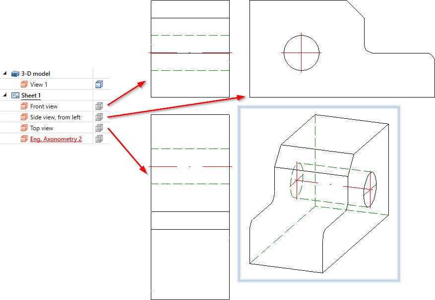
In the illustration, views of a 3-D model have been generated using the 4 standard views (3-D)  function.
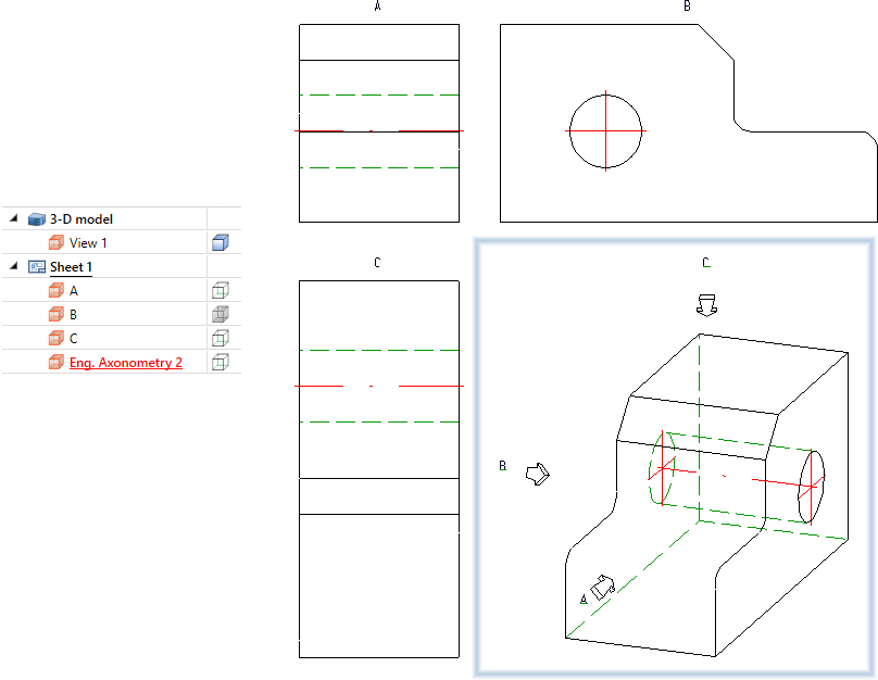
In the following illustration, the front view, the left side view and the top view have been marked according to the arrow method - with the axonometry as the original view.
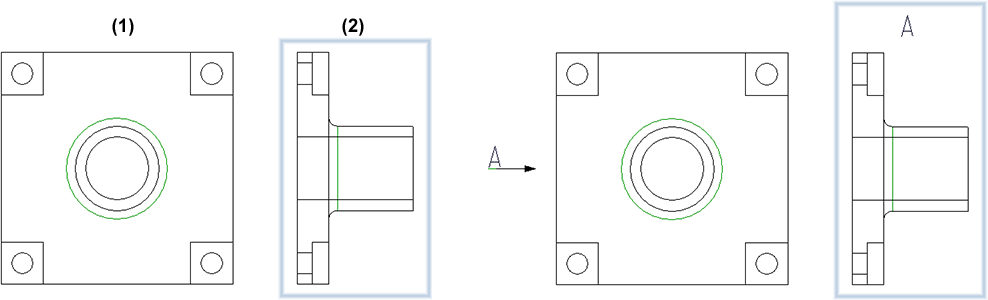
Example 2:
In this example, view (2) has been derived horizontally from view (1). On the right side of the image, view (2) has been marked using the arrow method.
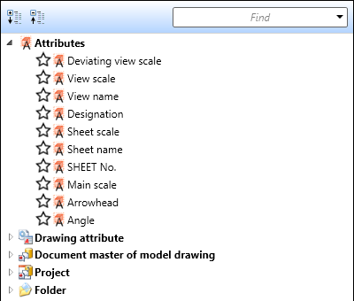
Before calling the function, activate the view to be marked. After calling the function, the dialogue window shown here is displayed.
![]()
Heading
In this area you define the heading for the active view. If a heading is to be output, activate the Heading checkbox and select the Position of caption:
- centred above the view or
- centred below the view.
If you do not want to use the view marking selected via General, click  and set the heading as in the annotation editor.
Determine the components that are to be output in the caption. These can be fixed texts or attributes. For example, the view name, designation, scale and - for views not derived in alignment direction - arrow and angle can be transferred to the caption.
The ISD-side default setting for the heading is the view designation. This is defined in the VIEWHEADER_A.FTD file in the HiCAD SYS directory. You can change this default setting by adapting the FTD file accordingly.
Original View
Click on ![]() and select the original view.
and select the original view.
Select the symbol for the viewing direction and set the corresponding parameters. If the original view is a 3-D view, e.g. an axonometry, the selection of the symbols will have no effect. In this case, the system will always use a 3-D arrow.
Determine the position of the annotation in the original view. The annotation can either take place
- in the extension of the viewing direction arrow or
- on the side, next to the viewing direction arrow.
If you do not want to use the view marking (of the derived view) selected via General for the annotation, click and adjust the annotation in the annotation editor.
The ISD-side default setting is defined in the VIEWORIGINLABEL_ARROW.FTD file in the HiCAD SYS directory.
You can change this default setting by adapting the FTD file accordingly.
The symbols of the annotation can be assigned to a specific layer. Select the desired layer by specifying the layer number.
General
Here you set the view marking for the active view.
If you have used capital letters or numbers in view markings in the drawing, HiCAD will automatically suggest the smallest capital letter or the smallest number not yet used for the view designation. Views that only have a caption (without a designation in an original view) are also taken into account. Whether a letter or a number is suggested depends on the last designation used.
The view marking can be inserted with OK and Apply.When using OK the dialogue will be closed afterwards.
To delete the marking of the active view, click on the  symbol and select the Delete view identifier
  function.
Functions for editing the view marking can also be found in the context menu.
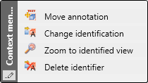
The Move annotation moves the complete view marking, i.e. symbol and text.
![]() Please note:
Please note:
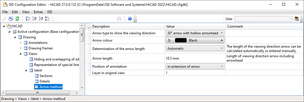
The default setting for the position of the caption can be defined under Drawing > Views > Ident in the Configuration Editor. The default settings for identification can be determined there under Drawing > Views > Ident > Arrow method.


View Functions (3-D) • Special Views (3-D) • Hatching in Sectional View and Cut-Out (3-D)