Dimension Orientation of Assemblies and Parts

Determining the dimension orientation
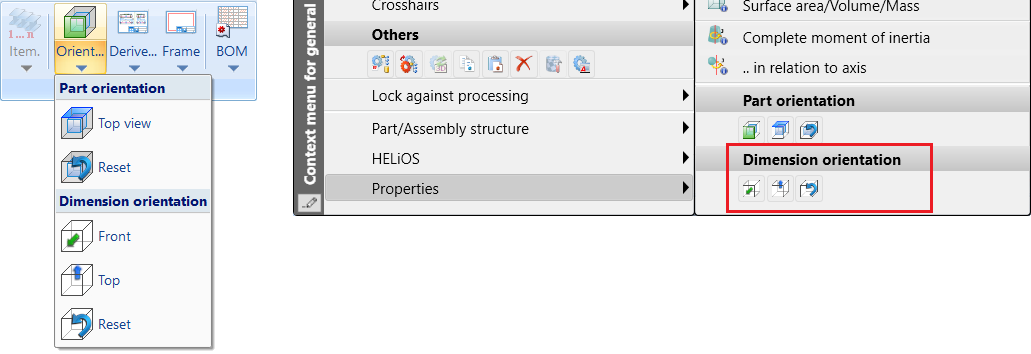
Drawing > Itemisation/Detailing > Orient... > Dimension orientation
Right mouse button > Properties > Dimension orientaion
The orientation of the bounding box (dimension orientation) plays a role in the calculation of dimensions, because it determines which values are assigned to the Length, Width and Height attributes.
The dimension orientation is determined according to the following priorities:
- The orientation is set manually via the functions under Properties > Dimension orientation in the context menu for parts and assemblies.
- The orientation results from the part orientation.
- The orientation results from the processing direction.
- The orientation results from the bearing bar direction. This only applies to gratings according to DIN 24537.
- The orientation results from the part coordinate system.
The first option that is available is used. Therefore, since each part and assembly has a part CS, there is always a usable orientation and the dimensions can be calculated.
If point 1 or 2 is used, length/height result from the front view and the width is perpendicular to it. This assignment is not configurable. If point 3 is used, the length results from the bearing bar direction.
For assemblies with an assembly main part, the following applies: If the orientation for the assembly has been set manually, this orientation applies. If no orientation has been set manually for the assembly, the orientation of the assembly main part will be adopted. The above sequence applies.
Whether the dimensions are visualised in the drawing depends on the setting in the Configuration Editor under System settings > Visualisation > Show dimensions of the active 3-D part.
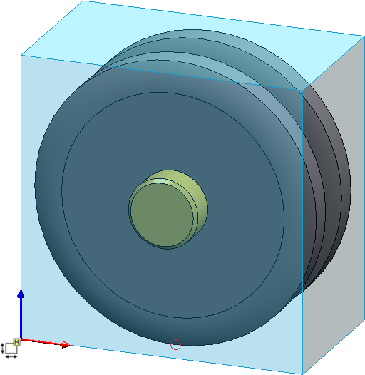
If the dimension display is active, the dimensions will be displayed in the form of a so-called bounding box (1). This is the smallest cuboid that completely encloses the part. In addition, the coordinate system is displayed on the bounding box. The coloured arrows of the coordinate system indicate the direction of the dimensions:
- Red: x-axis (length),
- Green: y-axis (width),
- Blue: z-axis (height).
Additionally, the bounding box is marked by a symbol (3) that indicates the up-to-dateness of the dimensions as well as the source of the orientation,e.g.
|
Meaning of the annotations |
|
|---|---|
|
|
The dimensions are not up-to-date. This occurs, for example, if you have selected the Only for automatic itemization setting under Modelling > Part properties > Calculate dimensions, since in this case the dimensions are only calculated / updated during the itemisation. |
|
|
The dimensions are up-to-date, the dimension orientation corresponds to the part coordinate system. |
|
|
The dimensions are current, the dimension orientation results from the bearing bar direction (only for gratings DIN 24537). |
|
|
The dimensions are up-to-date, the dimension orientation results from the processing direction. |
|
|
The dimensions are up-to-date, the dimension orientation results from the part orientation. |
|
|
The dimensions are up-to-date. The dimension orientation was set manually. |
|
|
The dimensions are up-to-date, the dimension orientation corresponds to the part coordinate system of the main part of the assembly. |
|
|
The dimensions are current, the dimension orientation results from the bearing bar direction of the assembly main part (only for gratings DIN 24537). |
|
|
The dimensions are up-to-date, the dimension orientation results from the processing direction of the main part of the assembly. |
|
|
The dimensions are up-to-date, the dimension orientation results from the part orientation of the main part of the assembly. |
|
|
The dimensions are up-to-date. The dimension orientation of the main part of the assembly was set manually. |


The dimension orientation assigned to a part is saved with the part.
Manually setting the dimension orientation
You can manually set the dimension orientation with the functions under Drawing > Orient... > Dimension orientation or in the context menu for parts and assemblies under Properties.
|
|
Orientation of the dimension by selecting the front side |
|
|
Orientation of the dimension by selecting the top side |
|
|
Reset dimension orientation (for manually set orientations) |


With the functions under Drawing> Orient... > Dimension orientation you can set or reset the dimension orientation of multiple parts one after the other without having to call the function again. You can then change the orientation of further parts or correct the orientation by selecting the previously selected part again. You can terminate the function with the middle mouse button.
In contrast, the corresponding functions in the context menu apply only to the active part and are automatically terminated.
|
Please note: Parts with the same item number have the same dimension orientation. In detail, the following procedure is used:
|
The functions also support multiple selection. The result log is displayed in a dialogue window. If the orientation
could not be assigned for all parts, a corresponding message will be displayed, e.g.
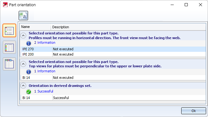
Changing the dimension orientation is generally not possible for parts that are locked against processing. However, they are considered when calculating the dimensions.
There is also a restriction for steel engineering plates, glasses and beams.
- Steel engineering plates, glasses
The height must point in the direction of the sheet thickness. - Beams
The length must point in the direction of the beam axis, the height corresponds to the web.
Examples
Example 1:
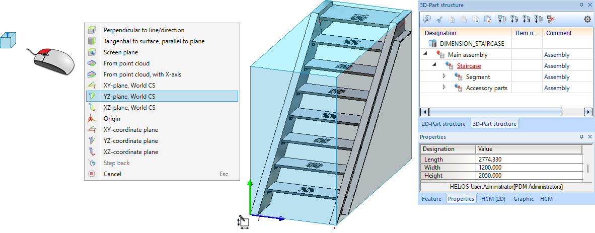
The figure shows an assembly (staircase) with automatic calculation of dimensions.
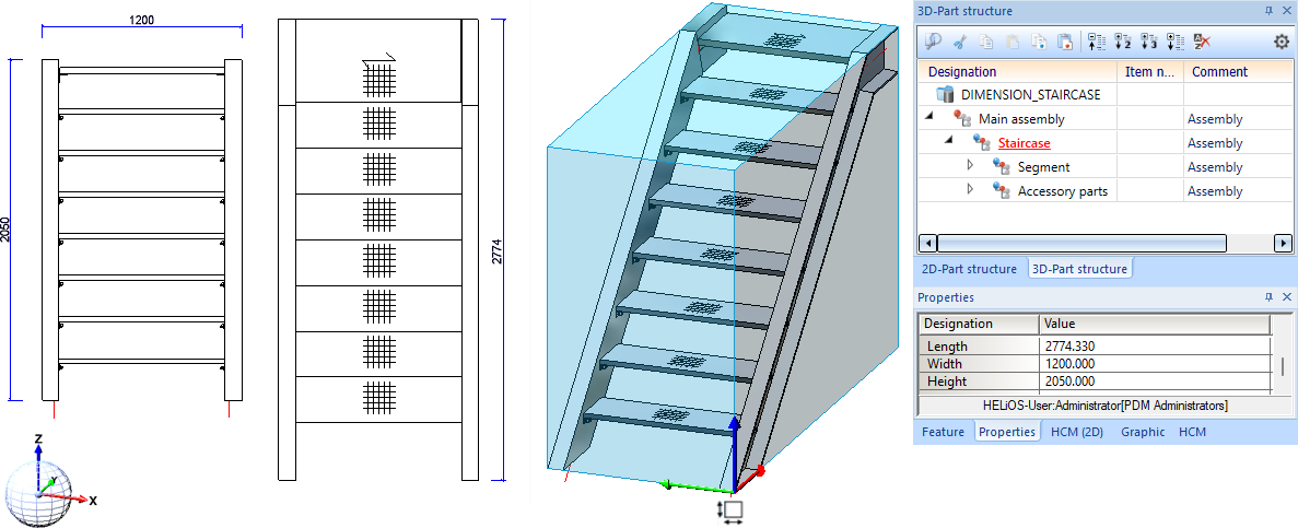
The dimensions for the width and height should be swapped. To do this, activate the assembly and select the function orientation of the dimension by selecting the top side  in the context menu under Properties and then select the YZ-plane of the world CS after right-clicking.
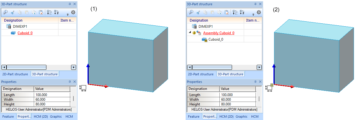
Example 2:
In the figure, a cuboid with length 100, width 60 and height 80 was entered (1) and then converted into an assembly (2). The assembly dimensions and dimension orientation correspond to those of the cuboid.
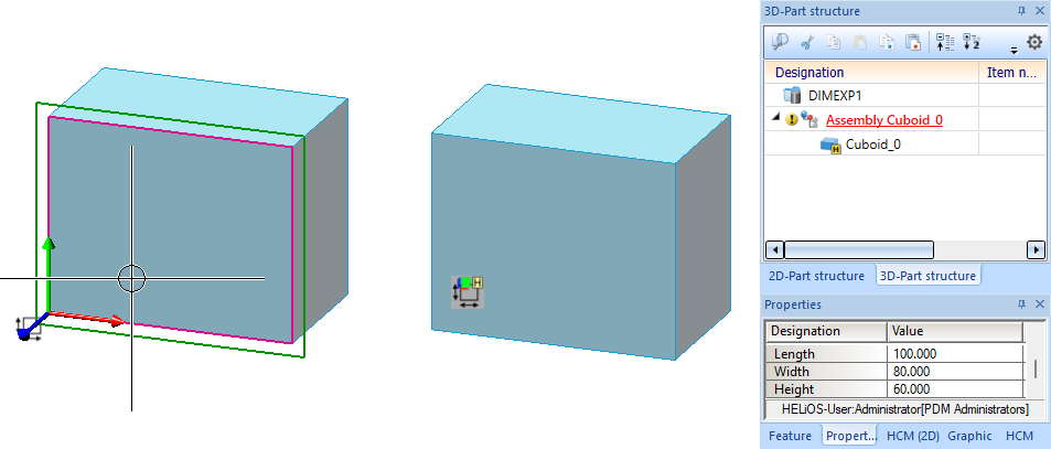
Now we change the part orientation of the cuboid by using the Define top view for derived drawings  function and selecting the marked plane. The assembly dimensions change.
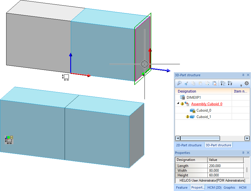
Now a second cuboid is installed as a sub-part of the assembly. The assembly dimensions are adjusted.
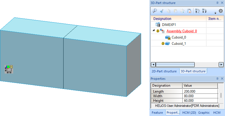
We change the part orientation of the second cuboid by using the Define top view for derived drawings function and selecting the marked plane. The assembly dimensions do not change as a result because the dimension orientation is given by the assembly main part - i.e. the first cuboid.
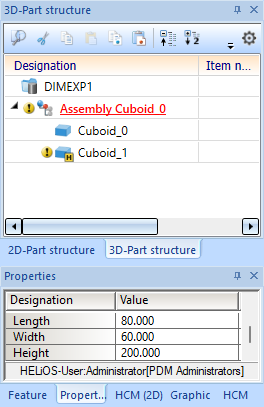
If you now convert the second cuboid into an assembly main part, the main part identifier of the first cuboid will be cancelled and the assembly dimensions will change.

Calculation of Assembly and Part Dimensions • Parts and Assemblies Not Relevant for Dimensioning