Chamfer Corners
3-D Standard > Process > Chamfer > Corners 
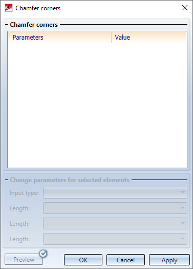
Use this function to chamfer three edges converging in a corner. For this purpose, the Chamfer corners dialogue window is displayed after the function is called.
The window is operated analogously to the chamfering of edges and surfaces.
In the drawing, select the corners to be chamfered. You can activate a context menu by right-clicking. There, you have the possibility to select all corners within a rectangle in one step via the Points in rectangle function. To do this, press and hold the CTRL key and use the left mouse button to draw the rectangle.
Each selected corner is entered into the list within the dialogue window. If you select a point in the drawing that is already included in the list, the entry will be removed from the list!
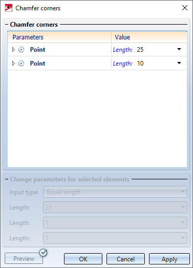
If you click on the entry of an entered point in the list within the dialogue window, the corresponding point will be visualised in the drawing.
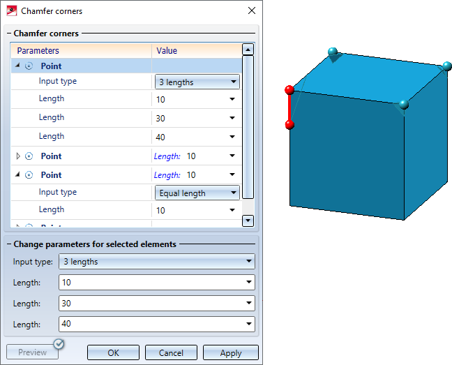
Two input types are available for chamfering corners.
|
Equal length |
The edges converging in the corner are chamfered with the same length. Enter the desired length. |
|
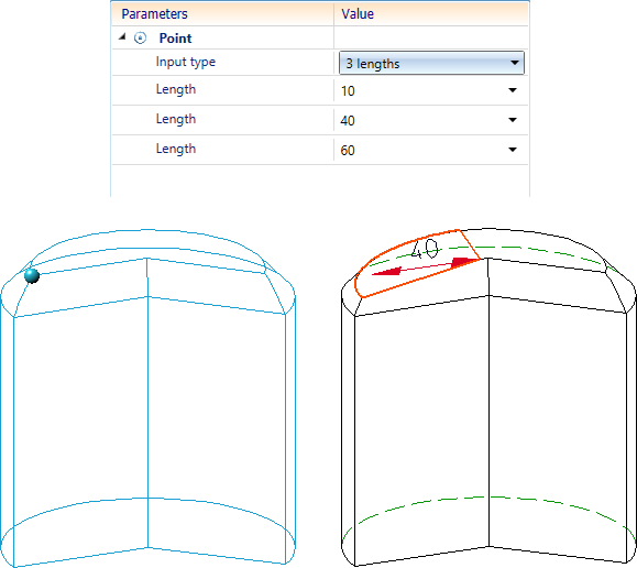
3 lengths |
Here, the edges converging in the corner are chamfered by specifying three length values. Enter the lengths. If you click on a length value within the dialogue window, the system will visualise which edge the value applies to in the drawing.
|
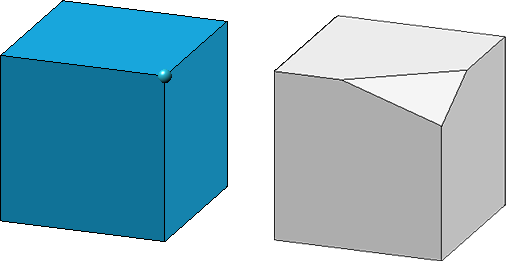
Chamfering a corner by specifying three lengths
It is also possible to select multiple corners within the list at the bottom of the dialogue window in order to change their parameters in one step. If you have selected different input types for these points, the text <Different values> will be displayed as a note under Change parameters for selected elements in the input fields.
All selected corners are chamfered with the values specified under Change parameters for selected elements when clicking the OK button.
![]() Please note:
Please note:
- The part to be processed must be a solid, i.e. the surfaces of the part must enclose a volume.
- The identified objects need to belong to the same part.
- As long as you do not leave the dialogue window via the OK or Cancel button, you can chamfer further corners.
- The value entries in the dialogue window can contain variables and formulas. In addition, you can call a context menu with further selection options by right-clicking. For example, you can also pick values in the drawing.
- The function can also be used via the HiCAD API.
- If theElement snapidentification mode is active, then the function is also available in the context menu for points.
- You can change chamfered edges / surfaces subsequently by using the Chamfer corners feature.
- Parametric dimensions are only displayed for straight lines.


Chamfer (3-D) • Fillet + Chamfer (3-D) • Process and Model Parts (3-D)