Boolean Operations
3-D Standard > Process > Add 
You use the
functions to perform Boolean operations.
The following options are available:
|
|
Creates a Boolean union of the active part and another part in the drawing. Sub-parts will also be considered. |

|
Add, without sub-parts Creates a Boolean union of the active part and another part in the drawing. Sub-parts will not be considered. |

|
Subtracts a part in the drawing from the active part. Sub-parts will also be considered. |

|
Subtract, without sub-parts Subtracts a part in the drawing from the active part. Sub-parts will not be considered. |
|
|
Subtracts an intersection from the active part. You can select the facets to which the resulting hole is to be parallel. |

|
Forms an intersection of the active part with another part in the drawing. Sub-parts will also be considered. |

|
Intersection, without sub-parts Forms an intersection of the active part with another part in the drawing. Sub-parts will not be considered. |
 Please note:
- The colour of the active part will always be applied to surfaces resulting from Boolean operations, i.e. the colour of added or subtracted parts will not be used.
- If you add to a solid a part of a different geometry type (e.g. a part with points or edges) that is no dummy, the part will be retained beneath the resulting body after the addition. From these retained parts, existing referencings and features will be automatically removed.
-
On the Simplify tab you will find the Merge all solids
 function. Use this function to merge all parts of the type "Solid" that belong to a part list (multiple selection) to one new solid by means of a Boolean operation.

Add
3-D Standard > Process > Add
You use this function to add the active part and any other part of the drawing. The active part is Boolean-unioned with the identified part.
- Identify the part to be added.
- If you want the part to be preserved after the operation, confirm with Yes.
Left: (1) Active cuboid, (2) Cone to be added
Right: Boolean union of the parts
Please note:
The adding of 3-D parts to a Steel Engineering parts may cause problems with subsequently called functions, e.g. mitre cuts, Steel Engineering connections, NC/NCX export, deriving of drawings, etc. Attributes (e.g. weight, length, etc.) may also be calculated incorrectly. In such cases, HiCAD will display the following warning message:
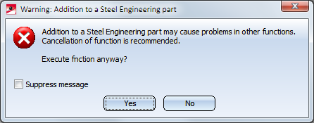
You can then decide whether you want to execute the function or not.
If you do no longer want this message to be displayed, activate the Suppress message checkbox. In this case, the adding will either be accepted or refused, depending on your last choice in the message window. Please remember that the checkbox status applies only to the current HiCAD session!
Subtract
3-D Standard > Process > Add  > Subtract
Subtracts any part of the drawing from the active part.
- Identify the part to be subtracted.
- If you want the part to be preserved after the operation, confirm with Yes.
Left: (1) Active cuboid, (2) Cone to be subtracted
Right: Result of the subtraction
Left: (1) Active cone, (2) Cuboid to be subtracted
Right: Result of the subtraction
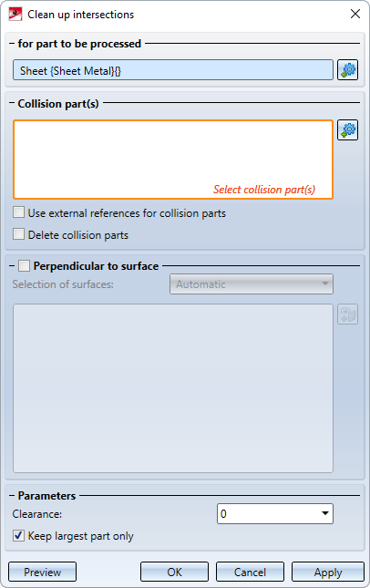
Clean up intersections
3-D Standard > Process > Add > Clean up intersections 
Sheet Metal> Further functions > Extras > Clean up intersections
With this function, collision parts, i.e. parts that cut through the active part, can be subtracted from the active part. If required, you can specifically define which surfaces should be taken into account during the clean-up. This can be useful, for example, if flanges or bend zones of a sheet metal part should be excluded from processing. Furthermore - in contrast to the normal subtraction - you can select the surfaces of the active part to which the hole created by the penetration should be perpendicular.
The function is identical to the function of the same name under Sheet Metal > Further functions > Extras. A detailed description of the function can be found here.
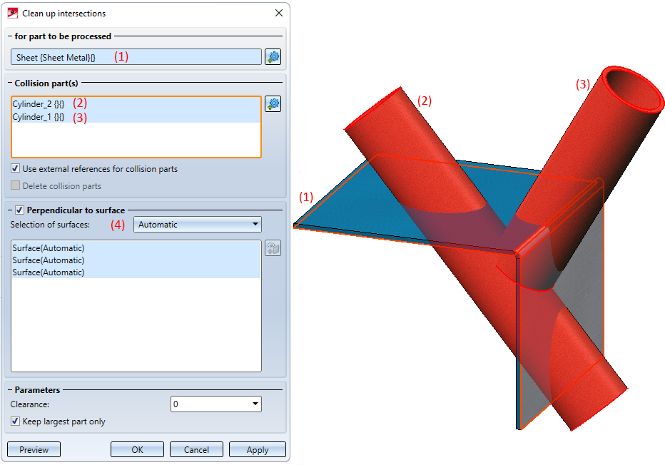
Example 1:
The pictured sheet metal part colliding with two cylinders should be cleaned up.
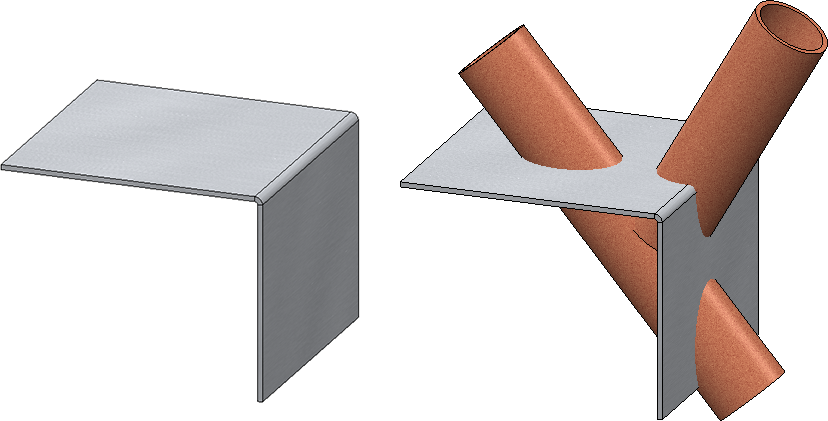
The processing should be perpendicular to the surface and all surfaces on the sheet should be processed. Therefore, the automatic surface selection is selected.
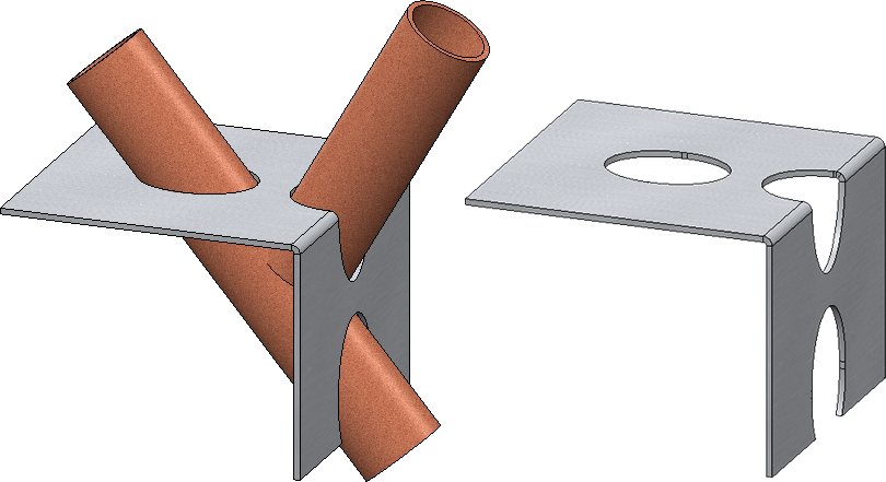
The result:
Example 2
The image below shows a cylindrical collision part (1) that intersects with a pipe.
Image A shows the result vertically cut with clearance. The outer surface (2) and the inner surface (3) of the pipe have been selected.
Image B shows the result without perpendicular cut.
![]() Please note:
Please note:
- If the active part is a Sheet Metal part, the Clean up intersections function on the Sheet Metal tab will be started automatically when you call this function.
-
The number of selected surface has a significant influence on the calculation time. This means that, for instance, in thin-walled 3-D parts (e.g. hollow cylinders) the accuracy will not be decreased if only one surface (inside or outside) will be selected.
Intersection
3-D Standard > Process > Add > Intersection
Creates the intersection of the active part with another part of the drawing.
- Identify the desired part.
- If you want the part to be preserved after the operation, confirm with Yes.
Left: (1) Active cuboid, (2) Cone for the section
Right: Result
