Clean Up Intersections
Sheet Metal > Further functions > Extras  > Clean up intersections
With this function you subtract the collision parts from the intersected part. These can be sheet metal parts, 3-D parts or hollow profiles, for example. If desired, you can exclude e.g. flanges or bend zones by selecting individual surfaces in the dialogue.
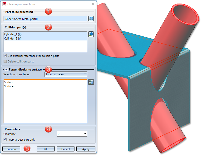
- Part to be processed
- Collision part(s)
- Perpendicular to surface
- Parameters
- Apply/discard value inputs
- Examples

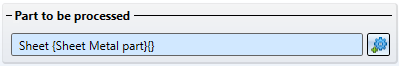
Part to be processed
The part to be processed can be, for example, a sheet metal part, a 3-D part or a profile. The entire part is always processed, i.e. if the intersection passes through several flanges, for example, all flanges and bend zones are automatically calculated. Of course, you can apply subtractions to individual flanges or bend zones in the Selection of surfaces area.
After selecting the function, the active part of the model drawing becomes the part to be processed. If you want to identify another part, click on the  icon for identification in the Part to be processed area .
Collision part(s)
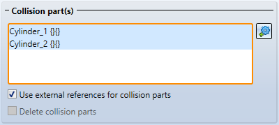
In the Collision part(s) area, you can select multiple parts or assemblies and define the further procedure for these parts.
With the option Use external references for collision parts, changes to the collision part will be tracked in the future. That is, if you change the radius of an intersecting cylinder, then after a recalculation of the Clean up intersection feature, the subtractions will be adjusted.
Perpendicular to surface
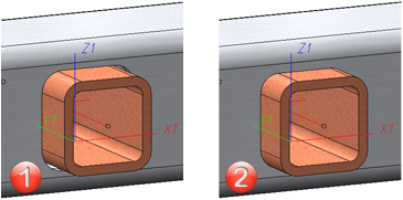
The intersection does not have to be perpendicular to the surface, it can certainly be done for lasers that cut at an angle.
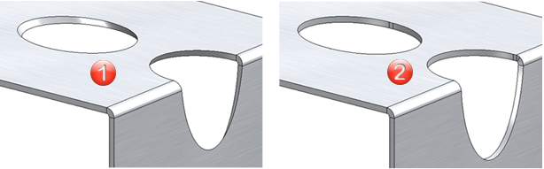
(1) Intersection parallel to the collision parts
(2) Perpendicular to surface
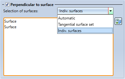
Selection of surfaces
When selecting the surfaces, you have several options:
|
Automatic |
Here, all surfaces of the part to be processed (e.g. flanges and bend zones) are checked for intersections by the collision parts. The surfaces with intersections are taken over into the surface selection. |
|
Tangential surface set |
After selecting a surface, all tangentially adjacent surfaces from the part to be processed are checked for intersections. |
|
Indiv. surfaces |
Here you select the surfaces to be processed individually. With a right click |
 you can delete the surfaces individually. By clicking on the
  icon you can select further surfaces later.
Parameters
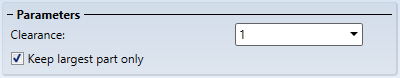
Clearance
The clearance determines the distance between the intersection and the collision part.
(1) With clearance, (2) Without clearance
Keep largest part only
By default, only the largest portion of the intersected part is kept after the clean up. In case you want to keep the small parts as well, the option can be deactivated.
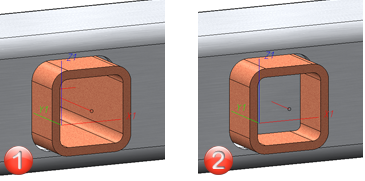
(1) Option Keep largest part only deactivated
(2) Keep all parts
Apply/discard value inputs
You can use the Preview button to check your settings and change them in the dialogue if necessary.
Once you have entered all the required data, the intersections can be installed. If you select Apply or press the middle mouse button, the intersections are installed, but the dialogue window remains open - unlike OK. This way you can change the data and assign them to other parts with Apply. If you leave the dialogue window with Cancel, the function is cancelled without installation or modification.
![]() Please note:
Please note:
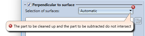
Incorrect entries are marked with the  symbol. Move the cursor over the symbol to display the error message.
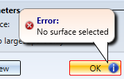
If the function cannot be executed with the entered data, the  symbol appears at the OK button . Move the cursor over the symbol to display the error message.
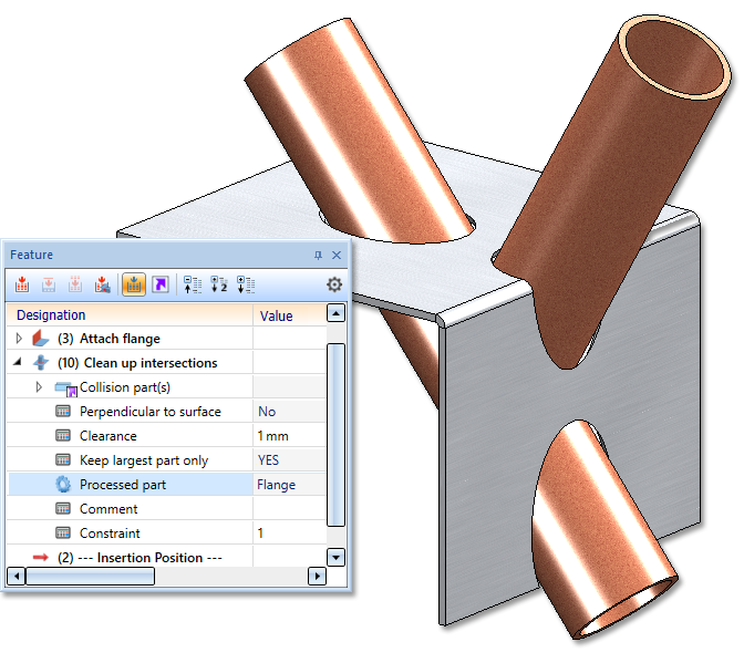
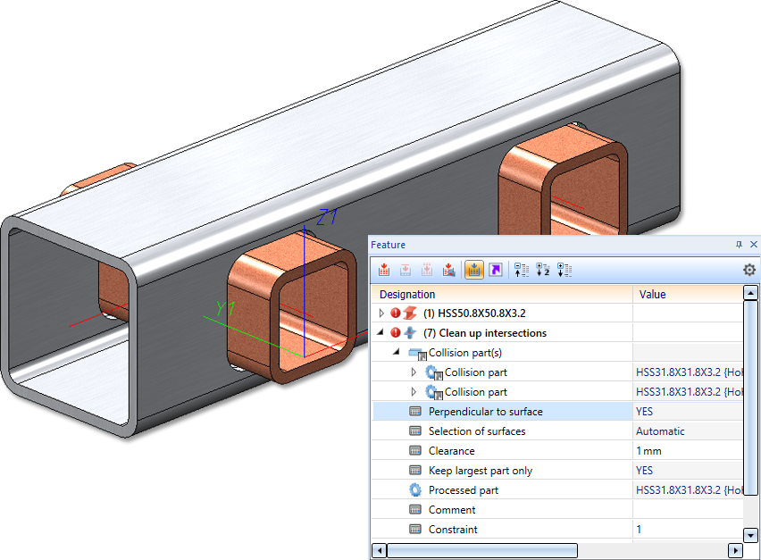
Examples: