Dialogue Window for Detail Views
Views> New >
Detail view 
You define the settings for detail views in the New detail view dialogue window, which is automatically displayed when you call the Detail view function.
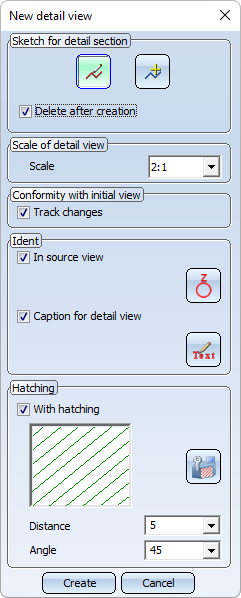
Please note that the hatchings of cut surfaces will consider the hatching settings of the drawing. You define these settings with the function Drawing > Properties > Hatching settings.
Topics:

Sketch for the detail area
The area of a detail view is based on a 3-D sketch.
|
|
New sketch |
Activate this icon to create a new sketch. |
|
|
Select sketch |
Activate this icon if you want to use sketches available in the drawing. Then identify the relevant sketch. |
|
|
Delete after creation. |
The sketch used is preserved even after the detail view has been created. |
|
|
The sketch used is deleted after the sectional view has been created. |


 If a sketch that has been parameterised with HCM constraints contains variables, these will automatically be defined as variables of the view. When using the sketch in a detail view, a sectional view or a cut-out. If you then change the value of the view variables, all views of the current drawing will be updated and the corresponding detail views, sectional views and cuts-outs will be adjusted accordingly. The original sketch, however, remains unchanged. This means that you can adjust view fast and easily without having to change the corresponding sketch.
Please also read the notes on the purposes and representation of sketches. Sketches with the purpose Part will be cut in detail views, sketches with the purpose Create/Edit will not be cut.
Scale
Here you can choose the scale for the detail view . The presetting can be determined in the Configuration Editor at System settings > Visualisation > Views > Scale for new detail views. Here you have the following options:
-
Increment scale
The next higher scale is used. This is the ISD default setting. For example, if the scale of the original view is 1:10, then the scale of 1:5 is preset for the detail view. -
Same as original view
The scale of the original view is used.
Conformity with initial view
The Track changes checkbox determines whether a detail view is associative to the initial view or not.
Associativity to the initial view means that the detail view inherits certain changes from the initial view. These are:
- cut-outs (including the creation and deletion of cut-outs),
- the section path (if the initial view is a sectional view) and
- hatchings of cut and cut-out surfaces.
Please note the following instructions if the checkbox is active (ISD default setting).
- Associativity must be set when defining the detail view. It cannot be set subsequently.
- Cut-outs and section paths that are inherited, i.e. originate from the initial view, cannot be edited in an associative detail view. This is only possible in the initial view. However, the detail view can also have its own cut-outs, which can then of course also be edited in the view.
- An associative detail view cannot change its initial view. Marking the detail outline is possible only in this specific initial view.
- When deleting the initial view, the associativity of the detail view is lost. However, the detail view itself does not change.
- The associativity of a detail view can be removed with the Change detail view function. This does not change the detail view, it just no longer follows the changes of its initial view. Cut-outs ans section paths originally "inherited" from the initial view become the detail view's "own" cut-outs and section paths. If the associativity to the initial view is removed, it cannot be set subsequently.
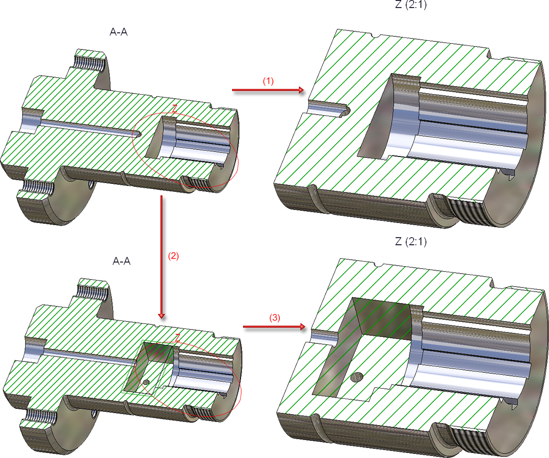
Example:
The figure shows a section view A-A with an associative detail view Z derived from it (1). Subsequently, a cut-out has been inserted into the sectional view (2). This cut-out is then transferred to the detail view after updating (3).
Existing detail views from older drawings (HiCAD 2023) are non-associative and cannot be set to associative.
Identification of detail views
In this area you determine whether the original view should be identified and whether the detail view should be provided with a caption. Activate or deactivate the corresponding checkbox.
|
|
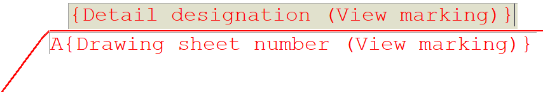
The original view (source view) is identified by an annotation and an outline. The ISD default setting is stored in the ViewOriginLabel_Detail.ftd file in the HiCAD SYS directory: |
|
|
Use the Change text- and line parameters button to customise the identification of the detail in the original view. |
|
|
If this checkbox is active, a caption will be generated for the detail view. The ISD default setting is: detail designation and scale. The detail designation is also used as the name of the original view. |
|
|
If you want to define an individual view caption, click on the Edit view caption button. |
Identification - Change text and line parameters

In the Detail identifier dialogue window, you can set the parameters for the identification of the original view individually.
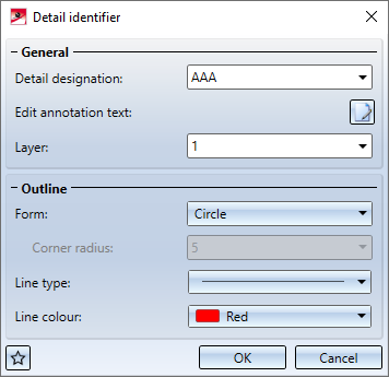
| General | |
|---|---|
|
Detail designation |
You determine the detail designation via direct input or selection in the listbox. It is also possible to use multiple letters or numbers here, e.g. AC. If necessary, HiCAD automatically suggests a letter (from the bottom to the top of the alphabet) or the smallest number not yet used as a designation. Views that only have a caption (without a designation in an original view) are also taken into account. Whether a letter or a number is suggested depends on the last designation used. |
|
Edit annotation text |
The ISD default setting for the annotation text is stored in the ViewOriginLabel_Detail.ftd file in the HiCAD SYS directory.
If you want to change the default annotation text, click on |
|
Layer |
Here, you define on which layer the detail identifier should be stored. |
|
|
|
| Outline | |
|
Form |
Various options are available for displaying the outline of the identification:
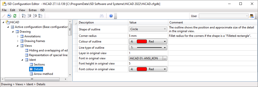
The ISD default setting is Circle. When calling this function for the first time within the current drawing, the settings from the Configuration Editor are used as default settings in the dialogue window (Drawing > Views > Ident > Details). For further calls of the function, the last used text and line parameters are used as default.
|
|
Line type Line colour |
Here, you specify the line type and colour of the outline shape. For the filleted rectangle, you can specify the corner radius. |
 . You can then define and format the text as in the
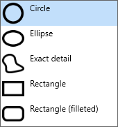
Edit view caption
If you do not want to use the ISD default settings for the caption of a detail view, you can define individual captions by clicking on  .
.
To do this, the View caption dialogue window is displayed, which is essentially the same as the annotation editor.
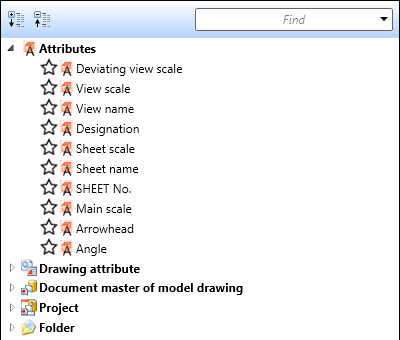
Determine the components that should be output in the caption. These can be fixed texts or attributes. For example, the view name, designation, scale and - if the view is not derived in alignment direction - arrow and angle can be transferred to the caption.
For captions in detail views, the template file VIEWHEADER_D.FTD is available in the HiCAD SYS directory. This file can be used to configure captions in detail views individually. By default, the FTD file is empty at first.
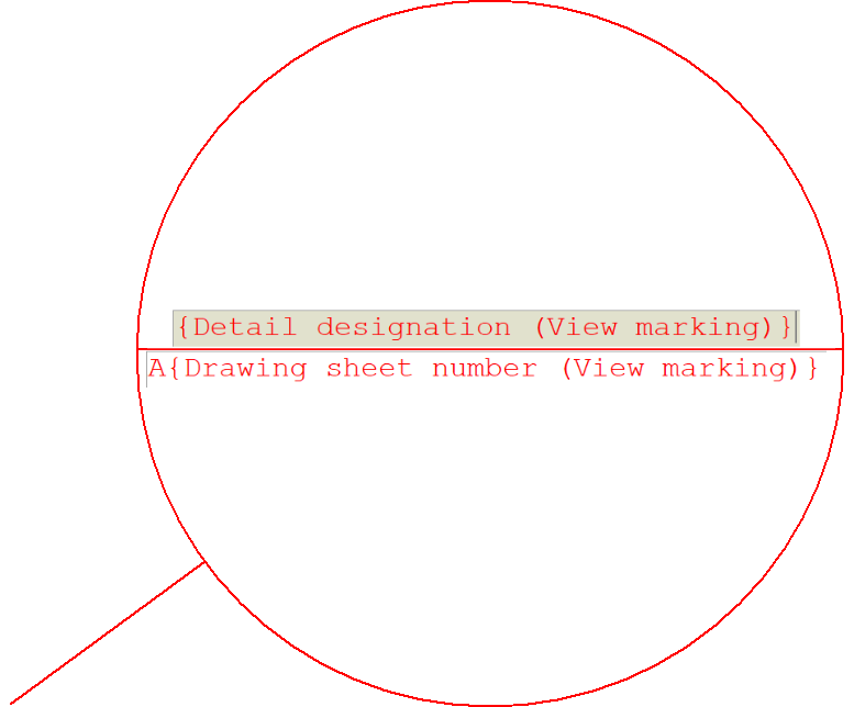
Example:
For the template file VIEWER_D.FTD, the displayed setting was saved.
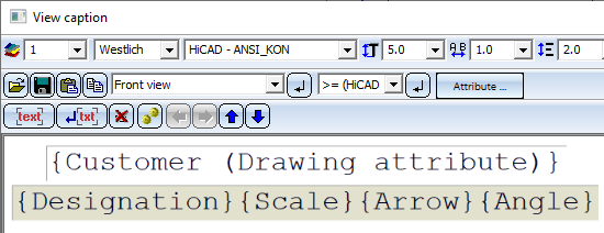
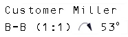
In consequence, the detail view will, for example, contain the displayed caption.
![]() Please note:
Please note:
The caption is automatically centred above the view. However, you have the option to move the caption afterwards.
Hatching
You can also display section surfaces of a detail view in hatched format. To obtain a hatched display of the section surfaces, proceed as follows:
- Activate the With hatching checkbox . The current hatching setting is displayed.
-
Select a different hatch pattern if necessary. Click on the Change hatching
 icon. The Hatch selection dialogue window is displayed. If you point the cursor on one of the patterns, more information about the hatch pattern is displayed. You can also zoom the display of the patterns by clicking on the magnifying glass symbol in the lower left corner.
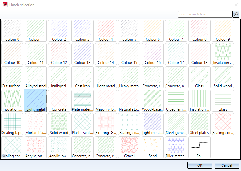
Select the desired pattern and confirm with OK.
- Define the hatching line spacing and angle.
The hatching of the cut plane is influenced by the settings chosen in the Configuration Editor, at Drawing > Views - Cut surface hatching.

Special Views (3-D) • Sectional and Detail Views (3-D) • Views (3-D) • Hatching Settings