Strap Joint
"Civil Engineering functions" docking window > Steel Engineering > Connections > Front side to web/flange side > Flange > Strap joint (2310)
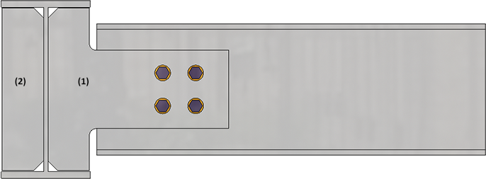
Use this function to connect two beams with a strap joint. This connection type consists of one or two bolted or welded straps and can be created with or without stiffeners. Supported for this connection are I-beams or U-beams or flat steels. You can also insert weld seams as well as holes for galvanisation (when connecting with stiffener).
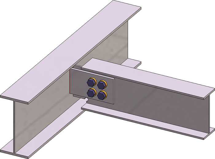
Beams connected with strap joint - Connection type: Notch)
Identify the two beams that you want to connect. The dialogue window for strap joints is displayed.
Click the Preview button if you want to display a preview of the connection based on the currently entered data. If you want to modify the current data, apply the required changes and click Preview again to update the preview. Click OK to insert the connection according to the current data and close the dialogue window. If you click the Cancel button, the window will be closed, and the specified or changed connection will not be inserted.
|
|
Selected parts Click on this symbol to display further information on the identified beams, e.g. material, dimensions etc. Value inputs are not possible here. |
|
|
The settings in the dialogue window can be saved as Favourites and reused at any time. To do this, click on the |


![]() Please note:
Please note:
- The straps and weld seams will be assigned to the beam to which the connection is made (2nd beam).
- Boltings are inserted as assemblies called Bolting. The assigning of these assemblies depends on the settings made on the Fixing tab. If the Loose part checkbox is active on that tab, the bolting will be assigned to a structure assembly called Loose parts. Otherwise, it will be assigned to the assembly of the 1st beam.
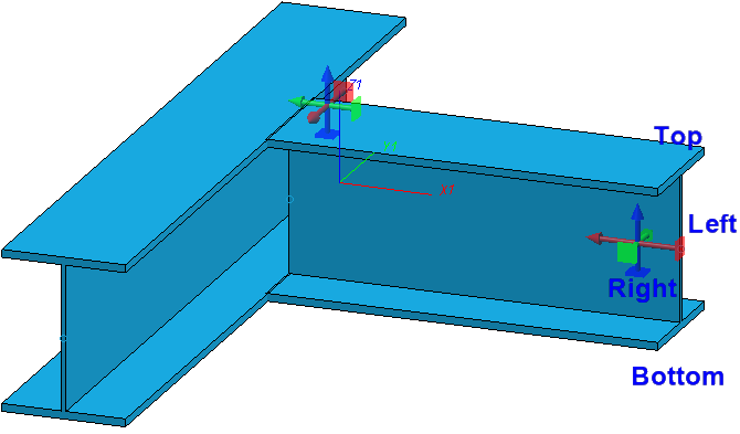
- During data input in the dialogue window, the directions will be indicated by appropriate texts in the model drawing. The texts are aligned in Z-direction.
![]() Important:
Important:
If not all options of the dialogue window are possible due to the position of the identified beams, this will be indicated in the dialogue window by the  symbol on the OK button. When you move the cursor over the symbol, an explanatory text will be displayed.

Connection type
Here you specify how the first selected beam is to be connected:
- Without stiffener,
- With stiffener or
- with Notch.
Depending on the selected option, input fields of other tabs will be greyed out. For example, if you have chosen the Notch option, no value inputs will be possible on the Stiffener tab.
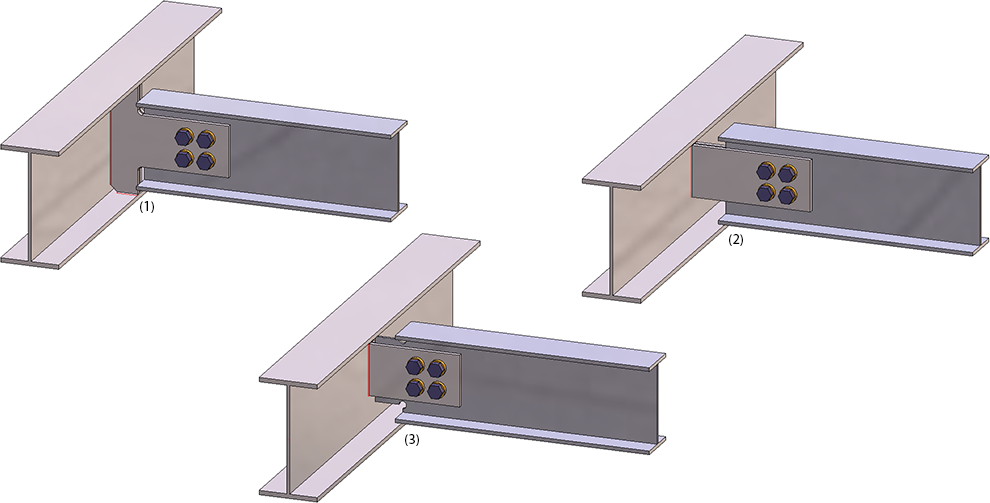
(1) With stiffener, (2) Without stiffener, (3) With notch
Configure connection
The configuration of the strap joint takes place via the tabs of the dialogue window:
Depending on the selected option, input fields of other tabs will be greyed out. For example, if you have chosen the Notch option, no value inputs will be possible on the Stiffener tab.
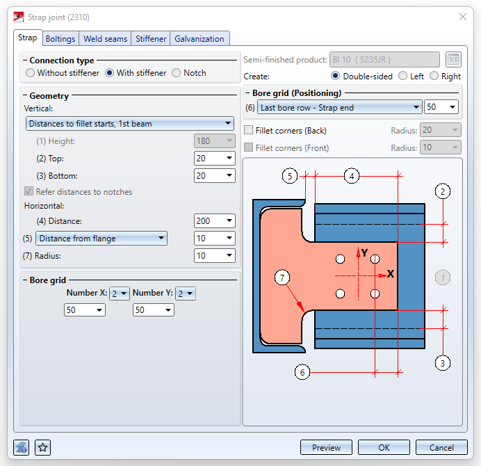
Strap
On this tab you define the geometry of the strap. It depends on the selected connection type which input fields will be available.
|
Semi-finished product |
Click on the |
|
Create |
Here you determine by activating the corresponding radio button whether the strap is to be created on both sides or only on the left or right on the 1st beam. |
|
|
The settings beneath Vertical and Horizontal determine the size and position of the strap. |
|
Vertical |
Here you specify how the height of the strap is to be determined by entering the required values:
Alternatively, you can also specify that the values refer to the notch by activating the Refer distances to notch check box. If, for example, you have selected Height, projection top beneath Vertical, then the value at the top is the projection of the beam if the checkbox is inactive, and the projection of the notch if the checkbox is active. |
|
Horizontal |
These settings are only available for the connection types Without stiffener and With stiffener. The distance here is the distance between beam start and strap end. Furthermore, the distance to the flange or the web can be specified here. For an insertion With stiffener you can also specify the Fillet radius for the stiffener. |
|
Bore grid |
The bore grid determines the arrangement of the bore pattern for the bolting. Specify the number of bores in X- and Y-direction and their distance to each other. If you want all bores running in one direction to have the same distance, you can achieve this by entering the distance value in only one field and clicking on the Equidistant |
|
Bore grid (Positioning) |
Beneath Bore grid (Positioning) you specify how the bore grid is to be placed on the strap. To do this, enter either the
In this section you can also specify whether the back and/or front corners of the strap are to be filleted. Filleting the front corners is only possible with welded straps (without stiffener / without notch). In this way, the rolling radii of the continuous beam can be taken into account. |
 symbol.
Notch
If you have selected the connection type Notch, you can specify the settings for the notch here.
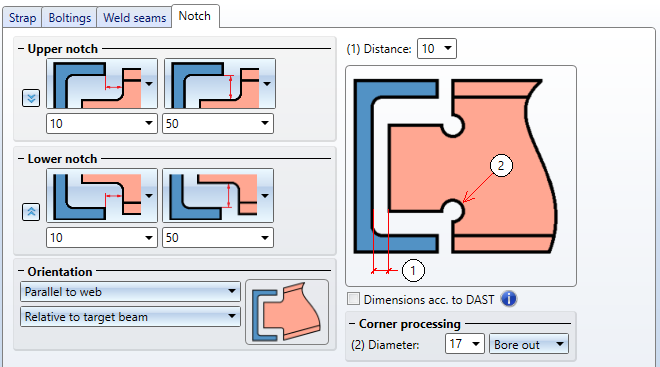
Upper/Lower notch
First, the distance between the end of the beam to be notched and the web of the connecting beam is required. The horizontal and vertical distances can be set separately for the upper and lower notch. Which distance is defined here is determined via the graphic selection boxes.
| Horizontal distance to | Vertical distance to | ||
|---|---|---|---|
|
|
Steg des Anschlussprofils |
|
Außenkante des auszuklinkenden Profils |
|
|
Flansch des Anschlussprofils |
|
Flansch Innenkante des Anschlussprofils |
|
|
Ende des auszuklinkenden Profils |
|
Flansch Außenkante des Anschlussprofils |


The settings for the upper notch can also be applied to the lower notch by clicking on the  icon and vice versa.
Orientation
The orientation can be parallel to the web or perpendicular to the beam axis of the target beam or the beam to be notched.
|
|
Parallel to web / Relative to target beam |
|
|
Parallel to web / Relative to notched beam |


Corner processing
Two variants for corner processing are available:
- Bore out und
- Fillet.
Choose the variant you require and enter the bore diameter or radius.
If the Dimensions acc. to DAST checkbox has been activated, the next higher values from "DSTV Typified connections in steel structural engineering" (Vol.1, Paragraph "IK Notches") will be used.
Stiffener
If you have selected the connection type With stiffener, specify the data for the stiffener here.
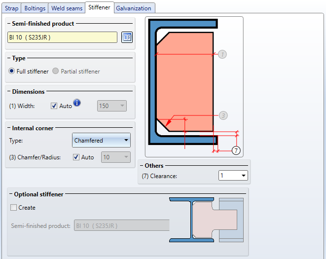
Click on the  symbol to select the desired semi-finished product for the stiffener from the catalogue.
Further parameters are:
|
Type |
Activate the corresponding radio button to determine whether a full stiffener or a partial stiffener is to be installed. |
|
Dimensions |
Full stiffener
|
|
Internal corner |
In these areas you specify the data for the internal corner. Select the Type:
Depending on the selected type, enter the chamfer length or the fillet radius. If you want HiCAD to determine the value, activate the Auto checkbox. |
|
Others |
Here you can enter a value for the clearance. |
|
Optional stiffener |
By activating this checkbox, a second stiffener can be installed. Select the desired semi-finished product for the stiffener by clicking on the For the optional stiffener, the Type selected under Internal corner is used. If the stiffener is chamfered, for example, this also applies to the optional stiffener.
(1) Stiffener; (2) Optional stiffener |
If the connection type With stiffener is selected for the strap joint, the Galvanization tab is also available.
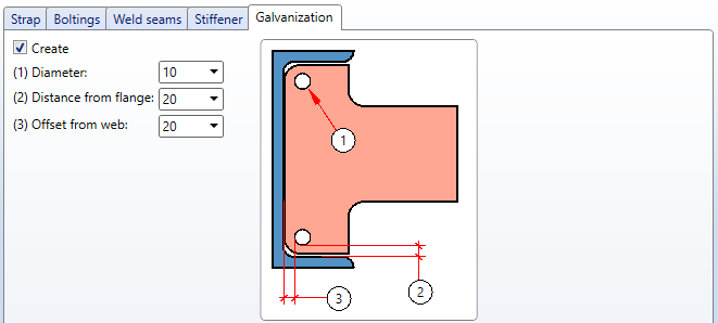
Here you determine whether the stiffeners are to be provided with holes for galvanization. Activate the corresponding checkboxes and enter the desired diameter. In addition, you can specify the minimum distance of the holes to the flange and to the web.
Boltings
On this tab you determine how the strap is to be mounted on the beam.
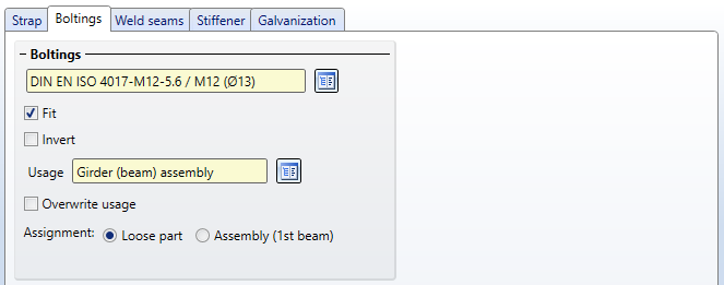
Here you can define boltings, e.g. type of bolt or screw, the bore diameter, etc. To do this, click on the symbol and then choose the components of the bolting. The default setting defined by the ISD is DIN EN ISO 4014-M16-5.6 / M16 ⌀ 17,5). You proceed in the same way as you would do with the Bolting function.
The bolting will only be inserted if the Fit checkbox has been activated. If you want to Invert the bolting, activate the same-named checkbox.
A usage can be assigned to these assemblies in the dialogue window of the connection. If one of these assemblies was already assigned a usage type, the usage type specified in the dialogue window was ignored in previous versions. The Overwrite usage checkbox can be used to specify whether the existing usage is to be kept or replaced by the usage type selected on the Bolting tab (or Fixing or Beam tab, depending on the connection).
The bolting will be inserted as an assembly called Bolting. At Assignment you determine, by activating the corresponding radio button, whether this bolting assembly is to be assigned to the assembly of the 1st profile or installed as a "loose part" (structure assembly)
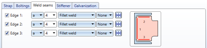
Weld seams
Here you determine, by activating the corresponding checkbox, whether the insertion is to be carried out with or without weld seams. For an insertion with weld seams, specify the following parameters:
- Type of thickness designation,
- Weld seam thickness,
- Weld seam type and
- Inspection category.

Connections + Variants (3-D SE) • Dialogue Window for Connections (3-D SE) • The Catalogue System for Connections + Variants (3-D SE)